BACKGROUND
Note: although a significant amount of information was included in this write-up, several critical details regarding manufacturing methods and techniques have been excluded due to their protected nature.
Revved Industries was a small manufacturing company which pioneered the production of hollow thermoplastic composite parts. The primary customer for Revved Industries was its own in-house brand of mountain bikes: Guerrilla Gravity (GG). The implementation of thermoplastic composites as opposed to traditional thermoset composites gave GG bikes the advantage of improved impact resistance as well as the potential to economically scale production (GG thermoplastic bikes manufactured in Denver were sold at a price-point which was competitive with thermoset bikes manufactured by factories in Asia). This cost-reduction was enabled by the use of dedicated tooling and automation.
The manufacturing process consisted of four steps: layup/consolidation, thermoforming/trimming, fusing, and finishing. The raw material was a dry prepreg unidirectional tape; lengths of the tape were dispensed and cut on-command by an operator who would place each length on a pattern and tack it to the other pieces to produce a layup. This layup was then heated and cooled under vacuum to consolidate all of the pieces into one unified laminate. The laminates were thermoformed on a large press before being fixed in a router to have the flashing trimmed off. Several different preforms were then assembled into a mold along with hardpoints (to provide solid material around bores and other mounting points) and a bladder, then moved into a heated press. During the fusing process, the assembly was heated to the melting point, internally pressurized by the bladder, and then cooled; this process fused all of the preforms together, allowing a hollow structure to be produced. After breaking down the mold, the bladder was removed to allow the part to be inspected prior to finishing (sanding, powder coating, and decal application).
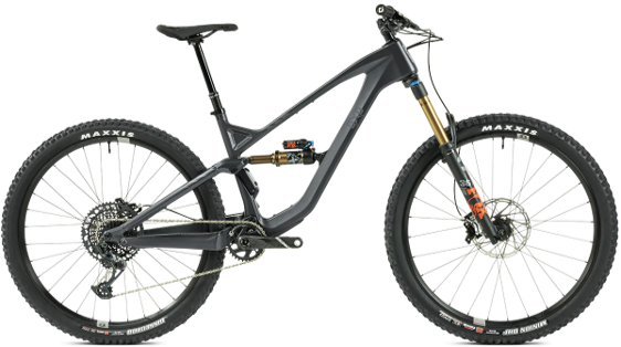
Guerrilla Gravity Mountain Bike
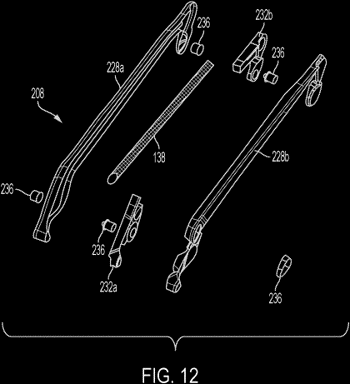
Assembly of various preforms prior to fusing.
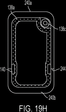
Diagram depicting the fusing process in which a bladder provided internal pressure during heating/cooling to fuse preforms together.
PROJECT SCOPE
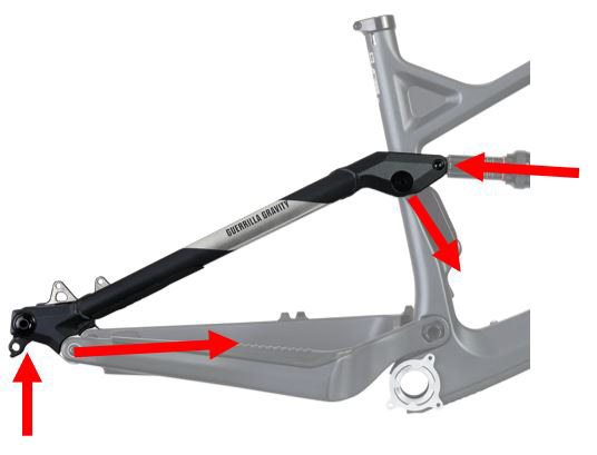
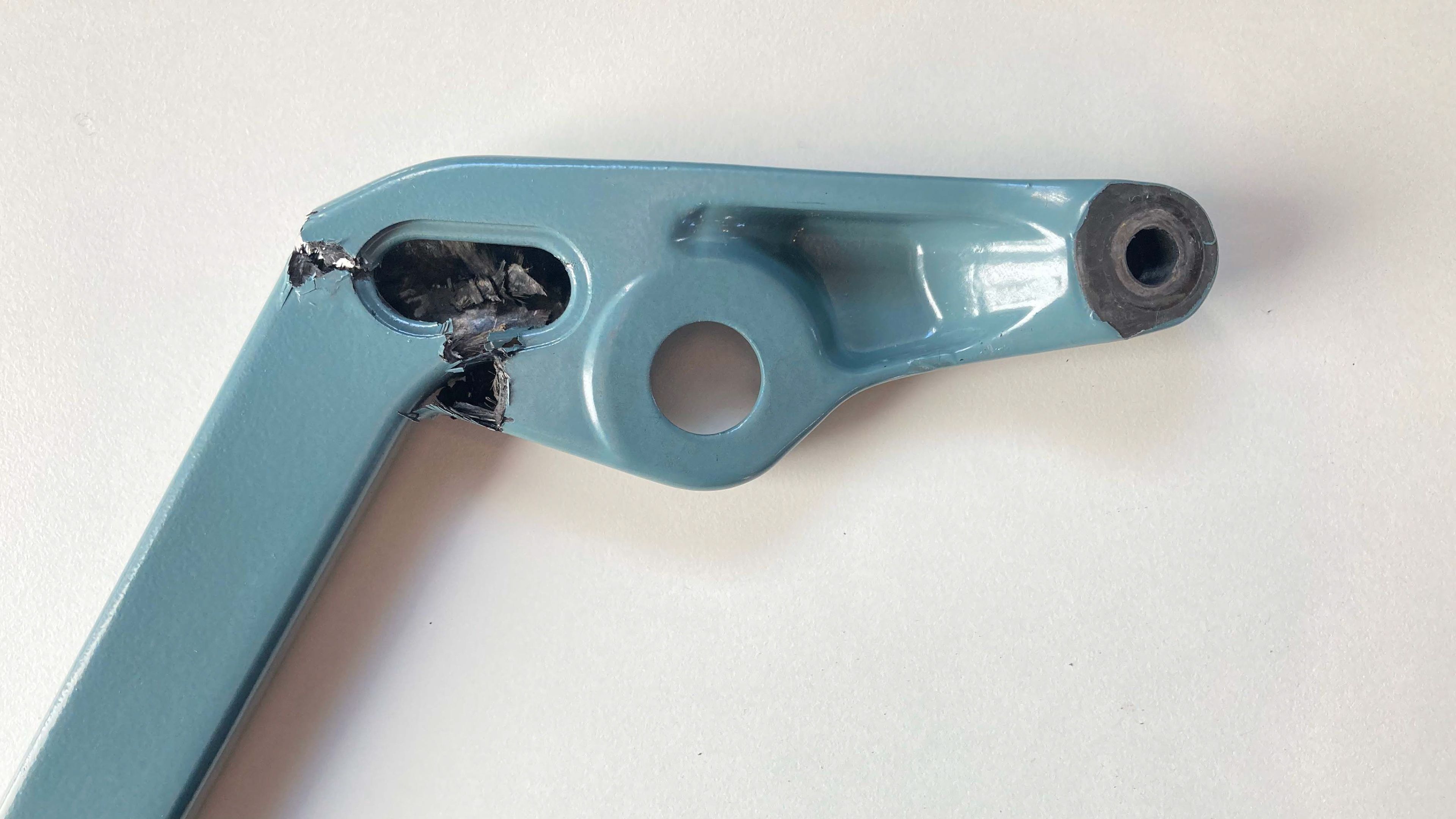
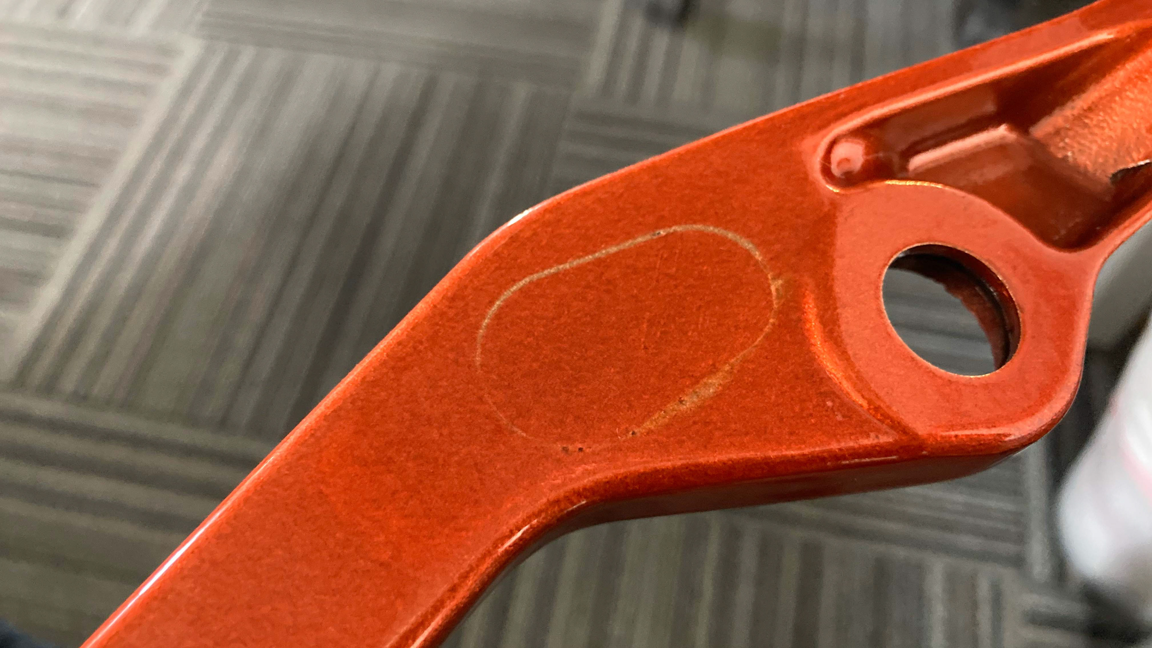
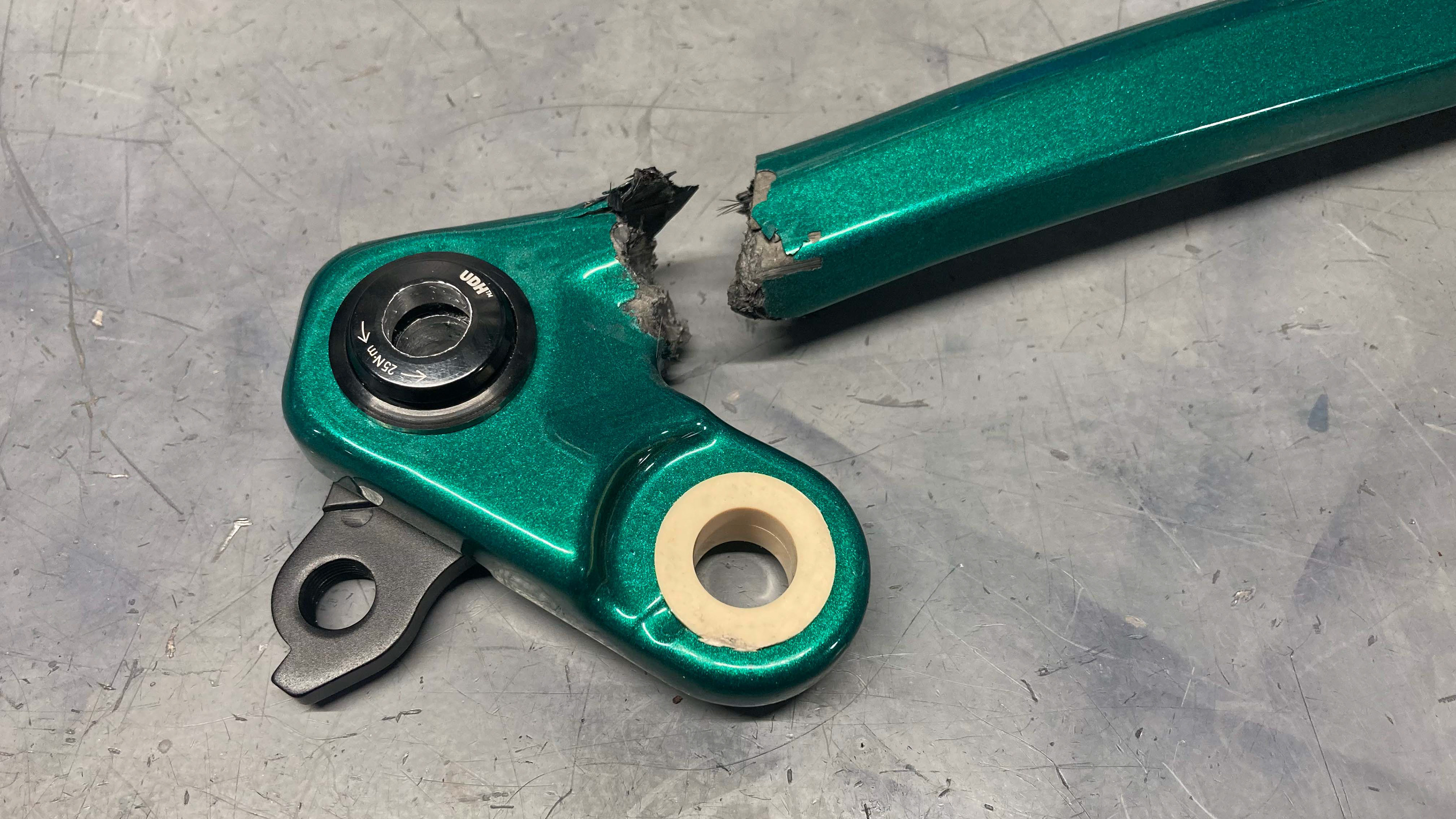
After being made responsible for future research and development projects at Revved Industries, my first task was to address field failures on the Guerrilla Gravity Trail Pistol. The GG models were built on a modular platform in which all bikes shared a common front triangle and swingarm; the Trail Pistol was the only bike in the lineup that featured carbon fiber seatstays (the remainder of the bikes all used welded aluminum seatstays which were heavier and did not provide as much damping). Although the seatstays were met with positive reception, roughly 5% of the parts were warrantied after fracturing on the trail. The cause was identified as a reduction in wall thickness during the manufacturing process, along with high inconsistency between parts. Unlike most other frame parts, the seatstays are primarily in compression, which makes them particularly failure-prone when they are manufactured using fiber composites. Although the minimum thickness of various regions along every part was being measured with a Hall effect sensor and recorded in a database, the inconsistencies between parts made it difficult to establish a strong quality control guideline to guarantee a reduction in field failures.
SOLUTION IDENTIFICATION
The first phase of the project involved identifying and quantifying the manufacturing steps in which material thickness was lost. The wall thickness varied significantly, both within each part and between each part, and sometimes resulted in a 70% reduction from nominal thickness. Prior to this investigation, it was assumed that nearly all of the wall thickness reduction occurred during the fusing step. To challenge this assumption, the wall thickness was measured in key locations after consolidation, preforming, and fusing (quality control during finishing was controlled by a separate department and was excluded from the scope of this project). Contrary to prior assumptions, it was found that the wall thickness was reduced by up to 40% during thermoforming. This expanded the scope of solutions to address both the thermoforming and fusing steps.
The second phase of the project consisted of exploring modified manufacturing techniques to identify any potential candidates for minimizing the reduction in wall thickness. These techniques included changing the layup schedule, adding reinforcements, tweaking the fusing recipe, and other changes. Several of these techniques showed moderate improvements; however, none of them were identified as a clear solution which could be implemented with resounding success. The primary culprits of the wall thinning were narrowed down to two process issues: (1) the thermoforming press was too powerful for the small cross-section of the seatstay preforms and (2) the bladders used in the seatstays were off-the-shelf profiles rather than custom-molded bladders, which provided uneven pressure to the walls during fusing. In consideration of time, the project scope was modified to focus solely on increasing the strength of the seatstays and to make that strength more consistent.
IMPLEMENTATION
After running a cost analysis, the decision was made to produce custom-molded bladders for the seatstays. This also provided an opportunity to redesign the hardpoints for light-weighting and to manufacture them with upcycled waste by utilizing a new injection molding machine which had just come online. To address the reduction in wall thickness during thermoforming, aluminum blocks were machined to act as bottom-out stops on the tools, controlling the thickness of the laminate during forming. A long-term solution to control the forming pressure was bookmarked as the controls engineer was pre-occupied with projects of higher priority.
The design process started by modeling the interior volume which would be available for the hardpoints and the bladder. From there, calculations were made to determine where the hardpoint/bladder interfaces should be to ensure that there was enough volume in the hardpoints to ensure that all mounting points were packed with solid material. The hardpoints were isolated and slightly modified ensure that they could be successfully molded. Nozzles were modeled onto the bladders before shelling them to the desired wall thickness.
Because the new hardpoints could be mimicked using existing materials and 3D printed prototypes, the bladder tools were made the top priority for production. As the tools were produced, they were immediately validated and used to fuse prototype seatstays. Several early issues were addressed by making minor modifications to the tools.
The injection mold design began by consolidating the parts onto as few molds as possible and by making decisions which simplified machining and reduced the number of unique parts from 21 down to 15. The availability of an in-house machine shop granted the design team liberties in trying new concepts which had never been tested before, such as nesting multiple parts on a single mold and using submarine runners to reduce post-processing. As with the bladder molds, the CAD models and drawings were provided to the machine shop and validated after production to verify fitment and proper filling. Several molds experienced minor problems such as insufficient filling, which was addressed by increasing the size of the runners and adding auxiliary runners to regions which were cut off by constricting part features.
TESTING AND VALIDATION
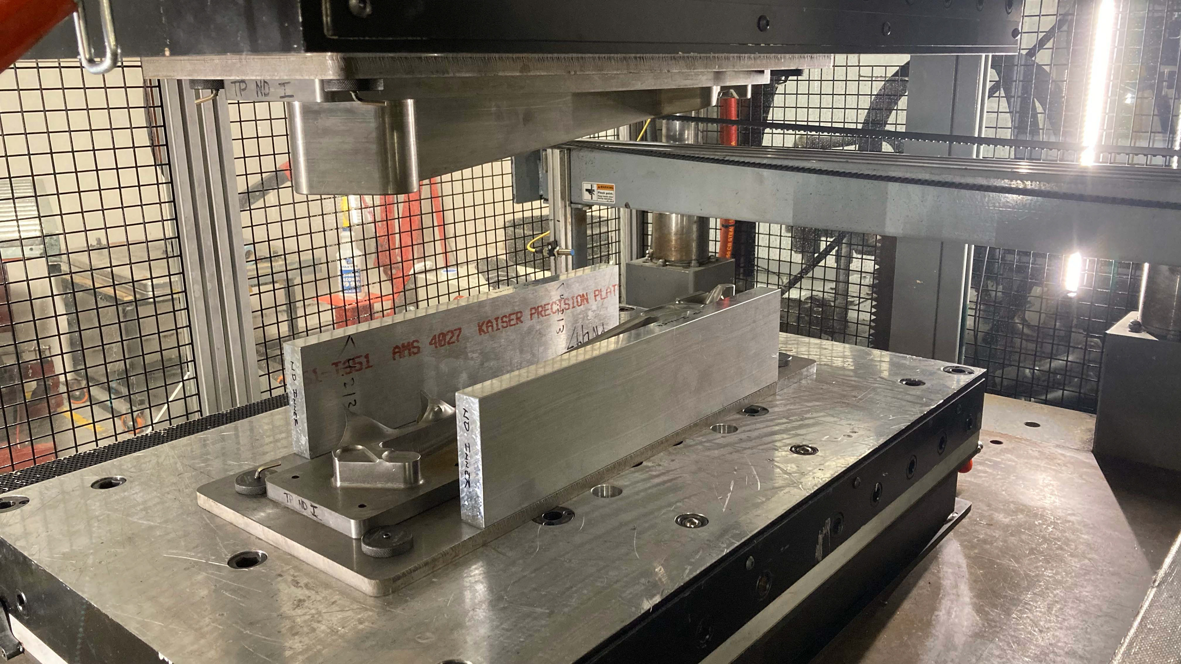
Following the production of the bladder tools and hardpoint injection molds, seatstays were fused and tested on an in-house impact tester. The test was designed to simulate a 95th-percentile rider landing in worst-case conditions for the frame (full front/rear bottom-out on rigid suspension). Throughout the testing process, three major issues were identified and addressed.
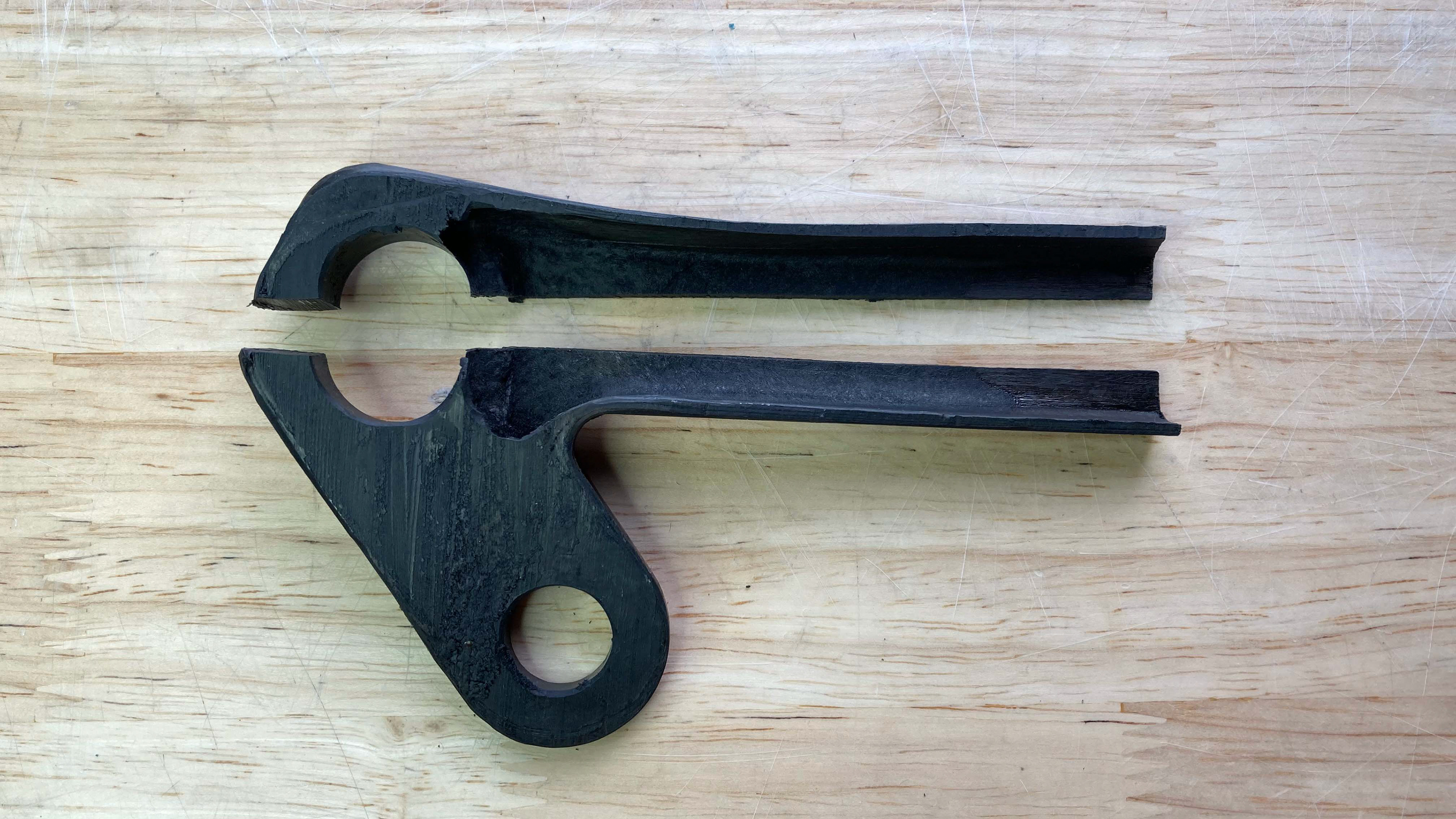
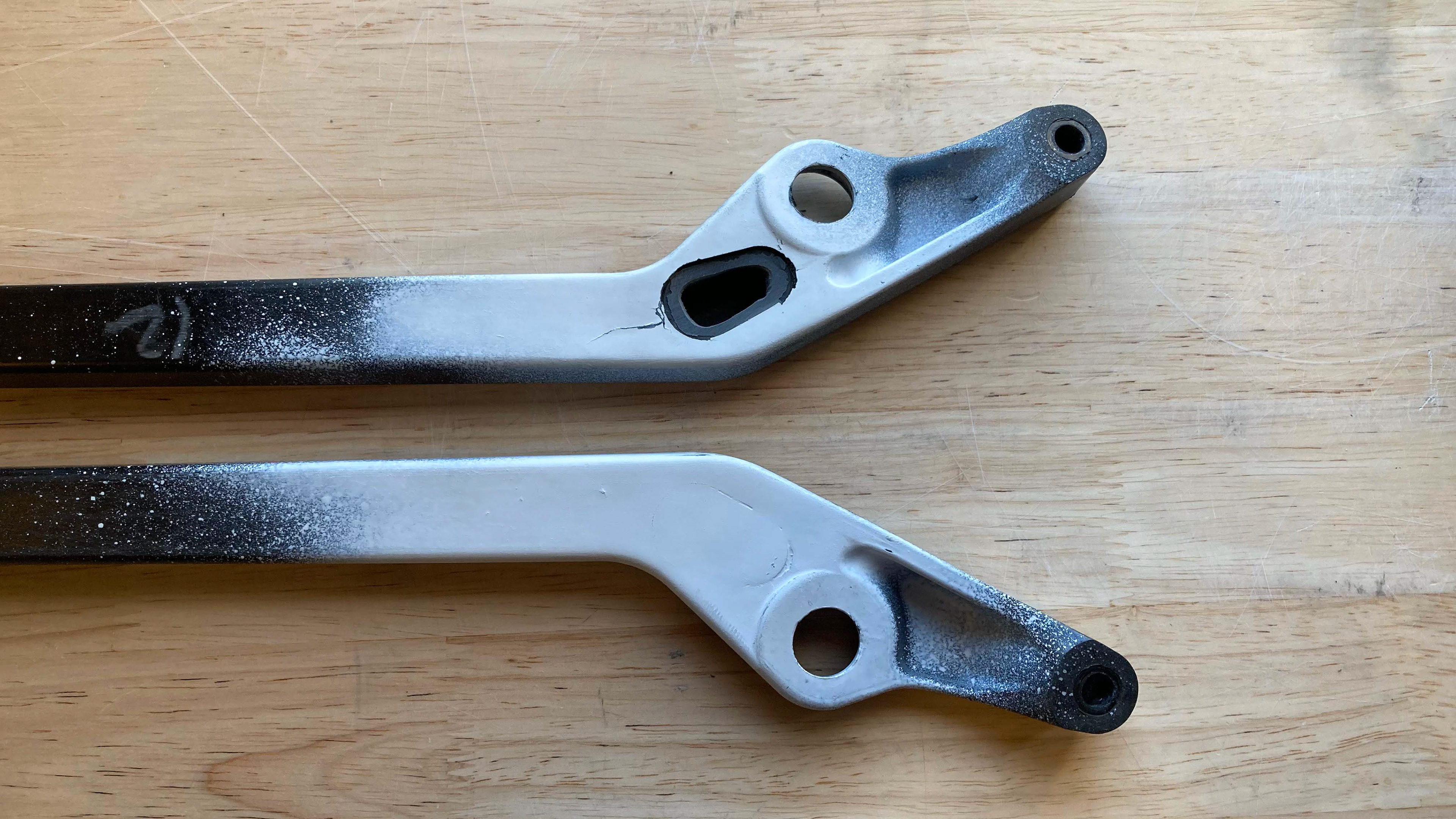
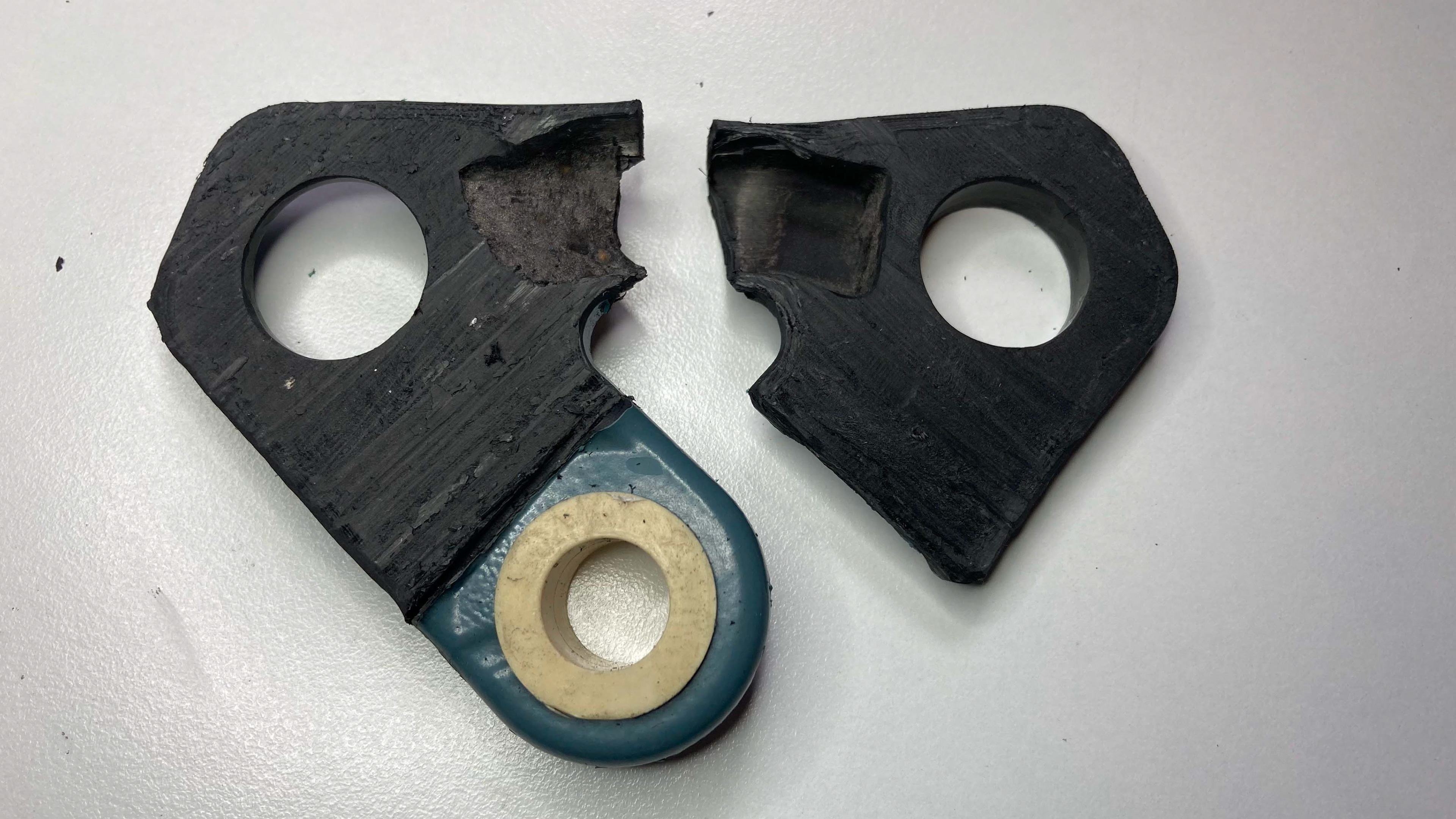
The first issue was thin walls on the drive-side rear axle bore. Seatstays were sectioned to reveal that there was a miscalculation on the volume of hardpoint which was required to fill the region, as well as a mis-prediction on how the injection-molded material would flow. A solution to move the interface was prototyped by adding more material to the tip of the bladder, cutting it short, and replacing the missing bladder volume with hardpoint material. The prototypes showed promising results, so the tools were sent back to the machine shop for modifications. Because the hardpoint solely gained material, these modifications only required milling out the molds; however, the bladder tools would require the addition of material to produce the correct shape. In order to avoid re-machining the entire tools, the section which required modification was isolated, milled out, and a core with the proper geometry was machined and pressed/bolted into place.
After addressing the first issue with the prototypes, a second issue was identified: the seatstays were stronger, but they did not meet the specification which was required. The bladder port acted as a stress concentration which severely limited the performance of the parts. The original design used a pliable rubber plug to cover this hole. To eliminate the stress concentration, a carbon fiber plug was bonded to the lip of the bladder port, enabling it to handle load. A proper adhesive and bonding procedure were identified and tested for both strength and post-finishing aesthetics. These additional processes added time, but significantly increased the strength of the parts.
As the bladder ports were reinforced with a bonded carbon cap, a third issue presented itself: some of the parts would fail below spec at the rear of the part (rather than at the neck where the bladder port was). This particular issue was very difficult to solve until the failures were traced back to the information on their production. It was identified that all of the failures occurred on sets with drive-side seatstays produced on the tools which were modified to address the first issue. In short, the prototype parts worked, but the production versions failed prematurely. Sectioning of the seatstays revealed that the bladder over-expanded in the rear on the production bladders. Sectioning of the bladders revealed that the tip of the prototype bladders was thicker than the production bladders. Therefore, additional material was milled from the bladder tools to mimic the wall thickness of the prototype bladders, and the issue was resolved.
RESULTS
After addressing all of the issues, the new seatstays were rigorously tested to evaluate their strength and consistency. The goals of the project were to achieve a minimum of 50% nominal thickness across the entire part; to exceed a specified energy level on the impact tester; and to be able to use the bladders for two cycles to hit cost targets. Of the final parts that were inspected, only 4/11 inspection areas had regions which dipped below 50% nominal thickness; three sequential sets of seatstays successfully exceeded the required impact energy, representing a roughly 30% increase over tests prior to the modifications; and methods were developed to use bladders for 2+ cycles.