Metallurgical and Materials Engineering
Thesis: Effects of Nickel Content on Rolling-Sliding Contact Fatigue of Carburized Steels
Introduction
Initiated in August 2017, the purpose of this project was to characterize the life-improving capability of nickel additions in carburized alloy steels under rolling-sliding contact fatigue. This project was of high interest to manufacturers of gears for heavy equipment. Nickel additions have been known to increase the fracture toughness of steels, making it a great additive for fatigue applications; however, it is relatively expensive, so it is not ideal for mass production.
Rolling-sliding contact fatigue (RSCF) is characterized by crack initiation/propagation by a combination of normal and tangent loads between two surfaces. Under contact fatigue, cracks are initiated in the material and propagated toward the surface, resulting in bulk material removal known as pitting and spalling. The normal load generates a Hertzian contact stress which peaks slightly below the surface, and the sliding component generates a shear stress which peaks at the surface and diminishes through the depth of the material. The addition of the sliding component increases the stress and shifts the peak stress closer to the surface; as a result, the crack propagation is accelerated and the distance to failure is decreased, effectively decreasing the fatigue life.
Although gears are most well-known for failing under bending fatigue, the precursor to this failure is contact fatigue. As gear teeth mesh, they transfer loads across the surfaces, resulting in contact stresses. Along the pitch diameter, the contact is pure rolling, similar to the stresses experienced by roller bearing elements; outside the pitch diameter, the contact has an additional sliding component. Under sufficient loads, the stresses can be great enough to cause pitting/spalling near the root of the tooth. These spalls act as stress concentrations which initiate final failure under bending fatigue.
Experimental Procedure
Four alloys were selected for comparison, each containing similar chemistry, but with varying nickel content. A geometry of 25.4 mm diameter by 152.4 mm length was selected to allow commercially relevant heat treatments to be applied without significant distortion. Bars of each alloy machined out of the mid-radius of as-rolled 5 in bar to avoid center-line segregation. These machined bars were gas-carburized, quenched, and tempered. A second set of the alloy with the lowest nickel content was run through a separate carburizing charge to match the carbon profiles of the rest of the alloys.
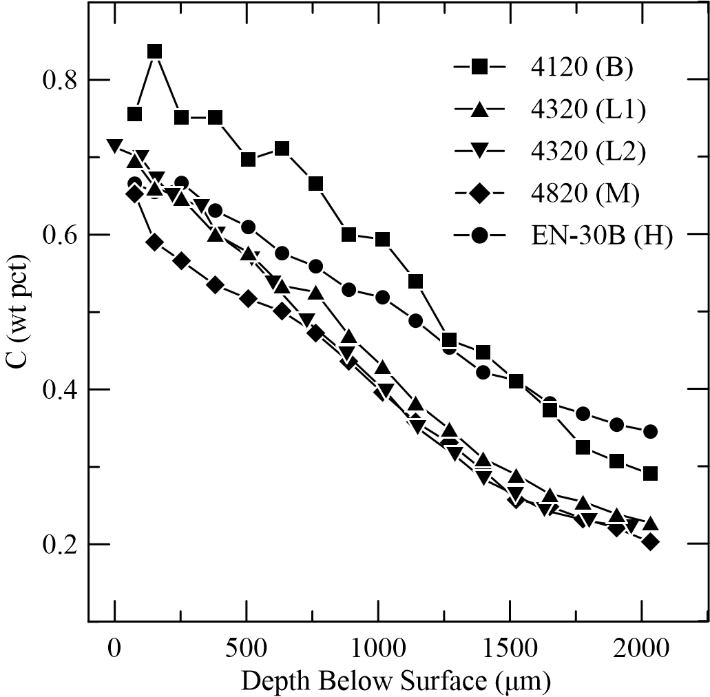
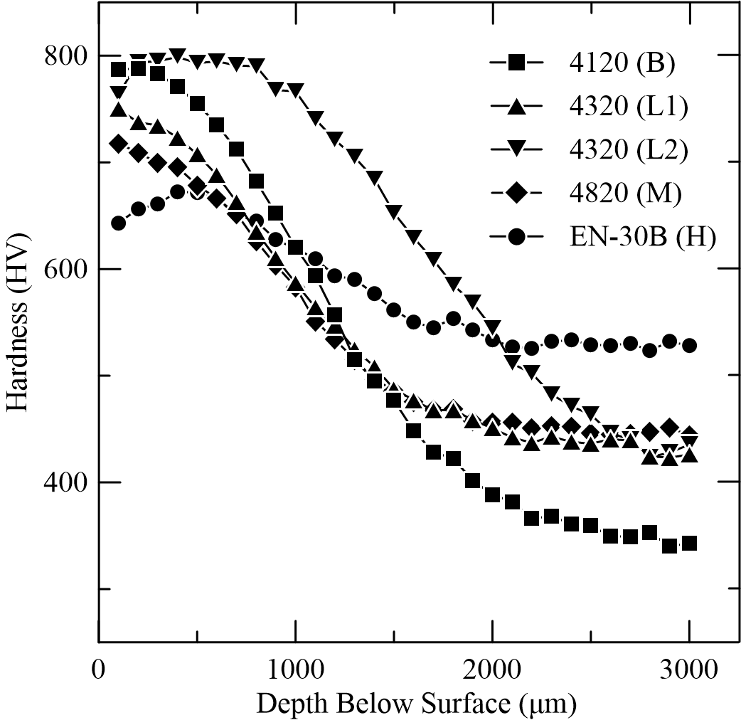
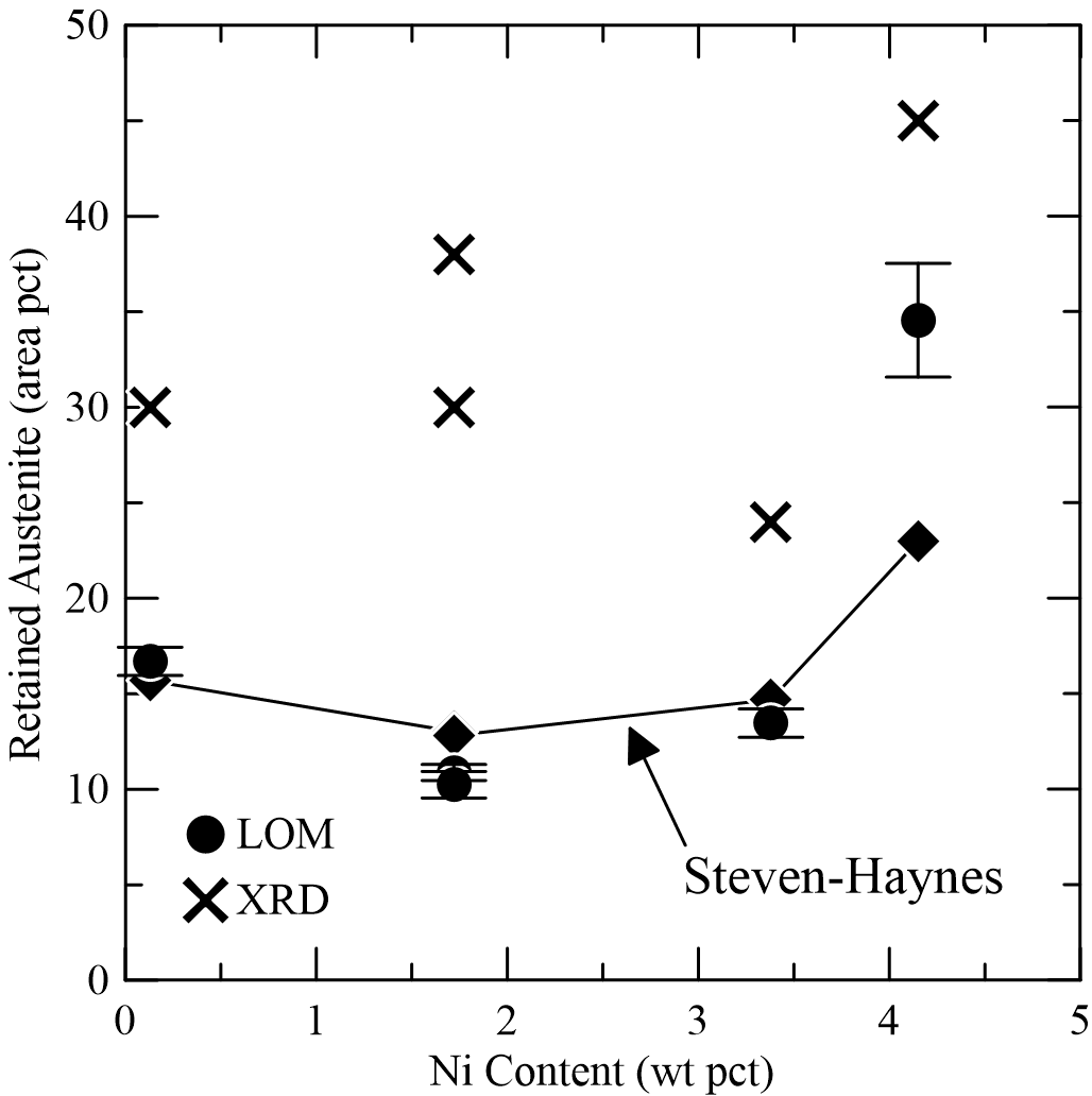
Prior to being tested, the as-carburized surface roughness of each bar was measured using an optical profilometer. A representative sample for each alloy was analyzed for several parameters, including carbon content, retained austenite, residual stress, oxide inclusions, and microhardness.

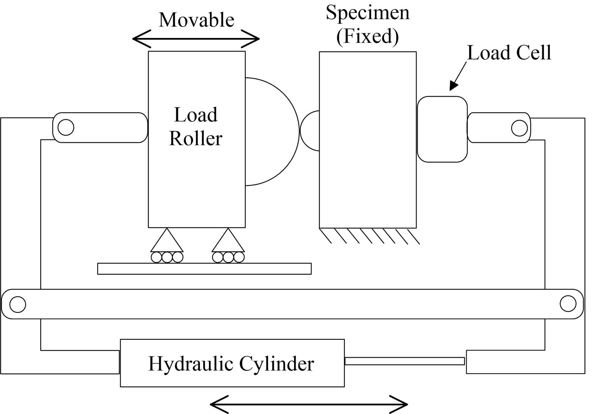
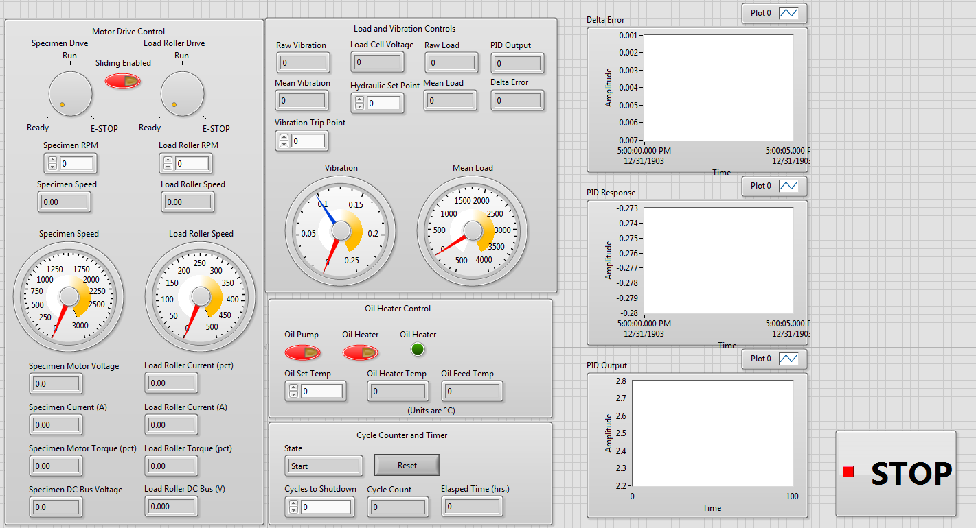
Testing was conducted on a custom modular unit which was designed and built by previous graduate students at Colorado School of Mines. The machine rotates the specimen and applies the loading using an opposing roller disc of 127 mm diameter and 12.7 mm width. A crown radius of 152.4 mm was ground on the contacting surface of the disc to eliminate stress-raising edge effects. The specimen was driven directly by a 7.5 hp electric motor, and the roller disc was driven by a 10 hp motor mated to a 5.4:1 reducing gearbox. The specimen driveshaft was designed to easily implement a torque sensor for calculating the tractive load at the surface. Load was applied by a hydraulic cylinder controlled by a servo-valve which adjusts the pressure based on feedback from an inline load cell. The entire system was controlled by a program written in LabVIEW, allowing the operator to easily modify all operating parameters.
After testing was completed, the specimens were cleaned, lubricated, and stored in anti-corrosive wrapping until further analysis. The surface roughness was once again measured along the wear track and compared to the initial surface roughness. Images of the pits were captured using a light-optical digital microscope with 3D image stitching as well as an environmental scanning electron microscope (ESEM).
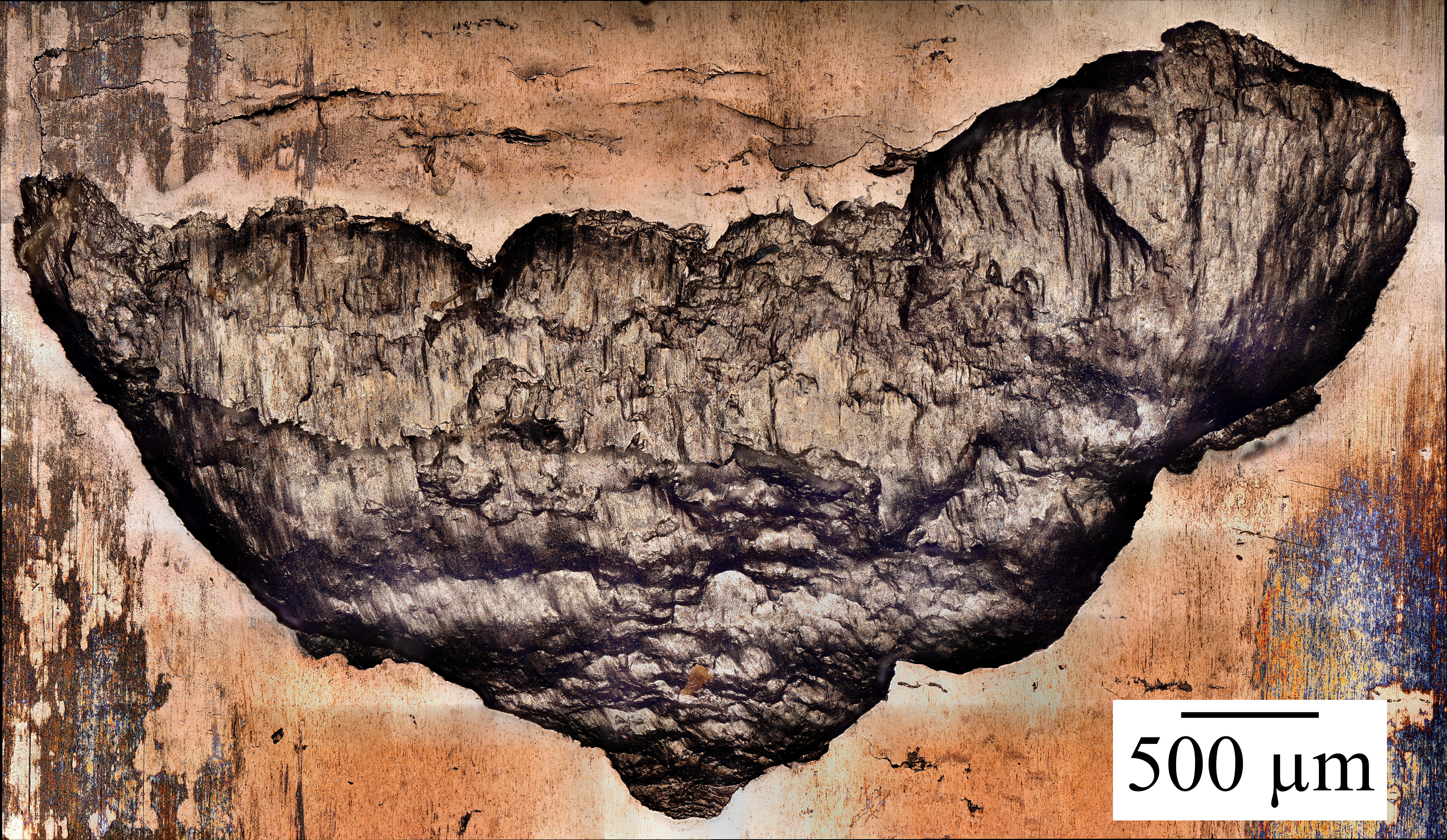
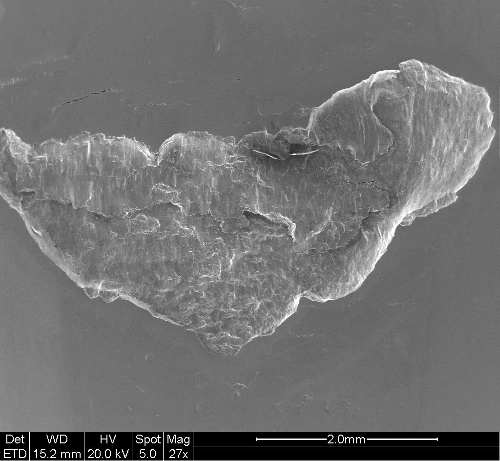
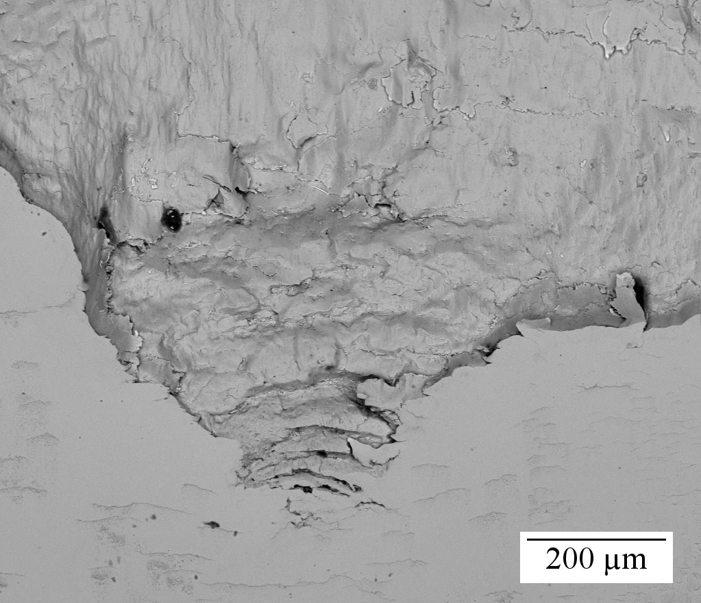
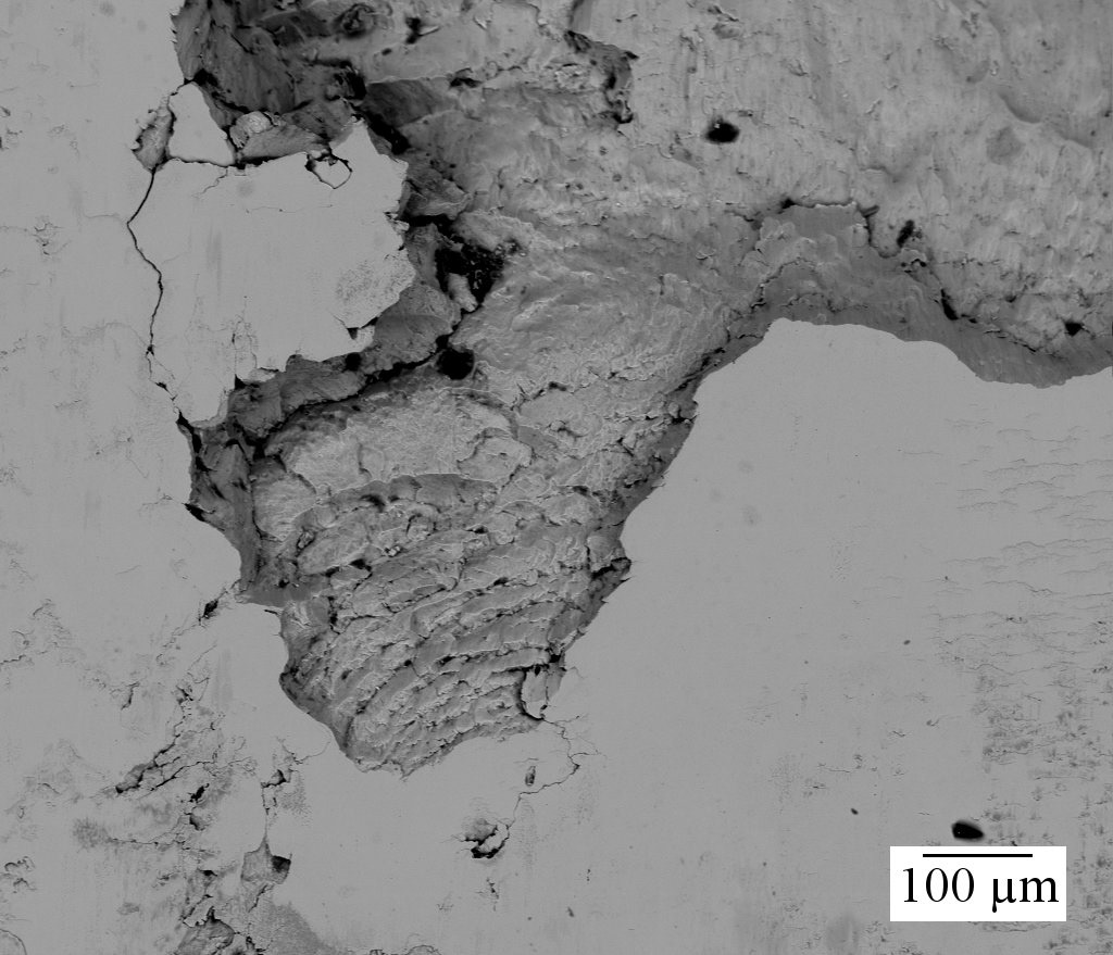
Microscopic image of a spall which formed under rolling-sliding contact fatigue. Left image captured using a Keyence VHX-5000 digital microscope. Right image captured using an FEI Quanta 600I Environmental SEM.
Results
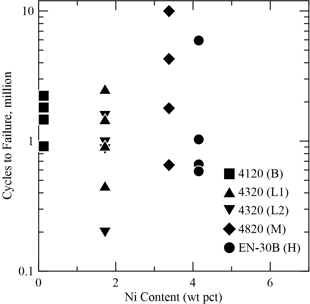
Data collected during the tests was processed in MATLAB and used to generate multi-variable regression models of the fatigue data. The fatigue life was plotted as a function of several variables; however, no strong correlation was found in any of these models.
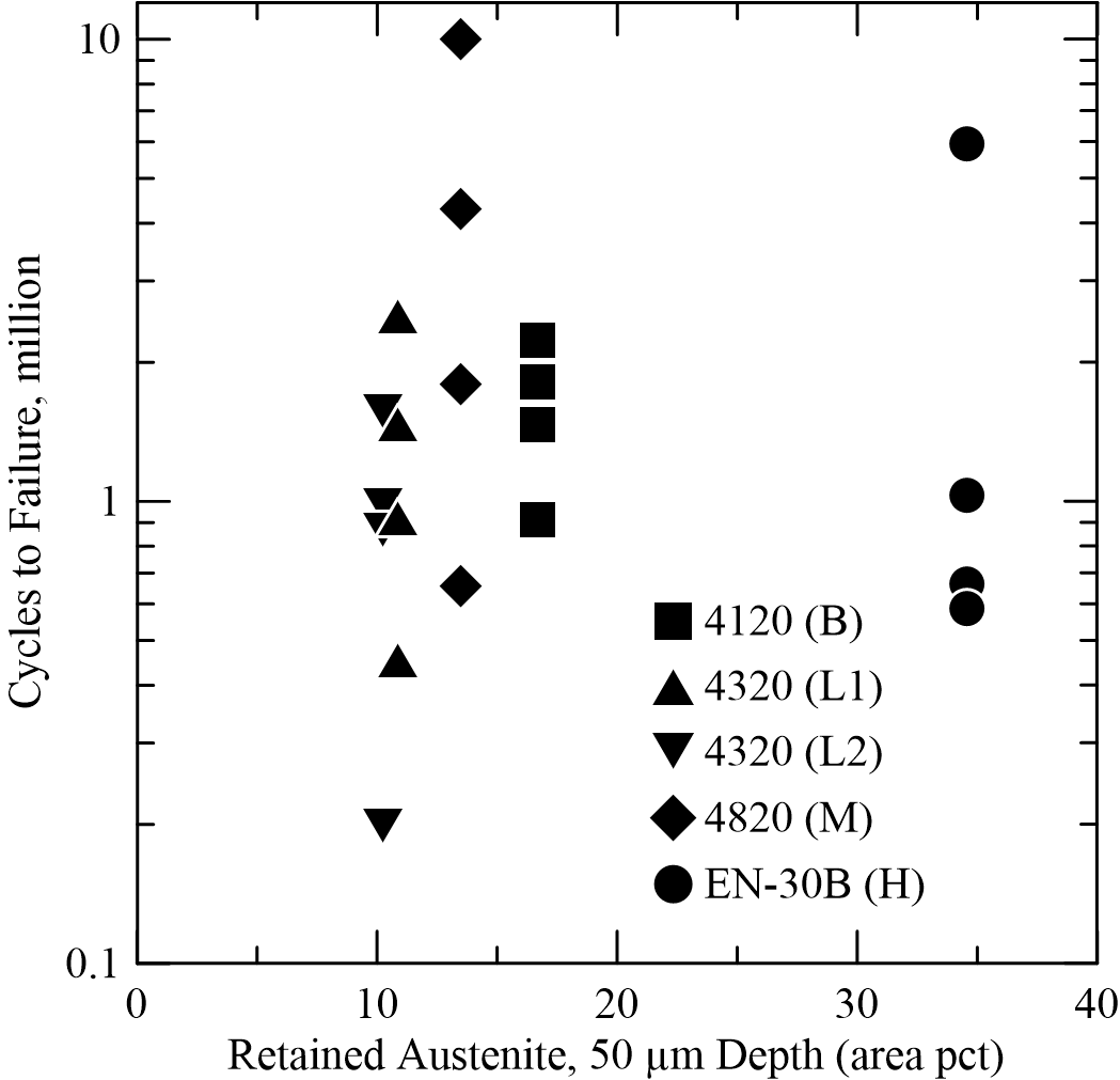
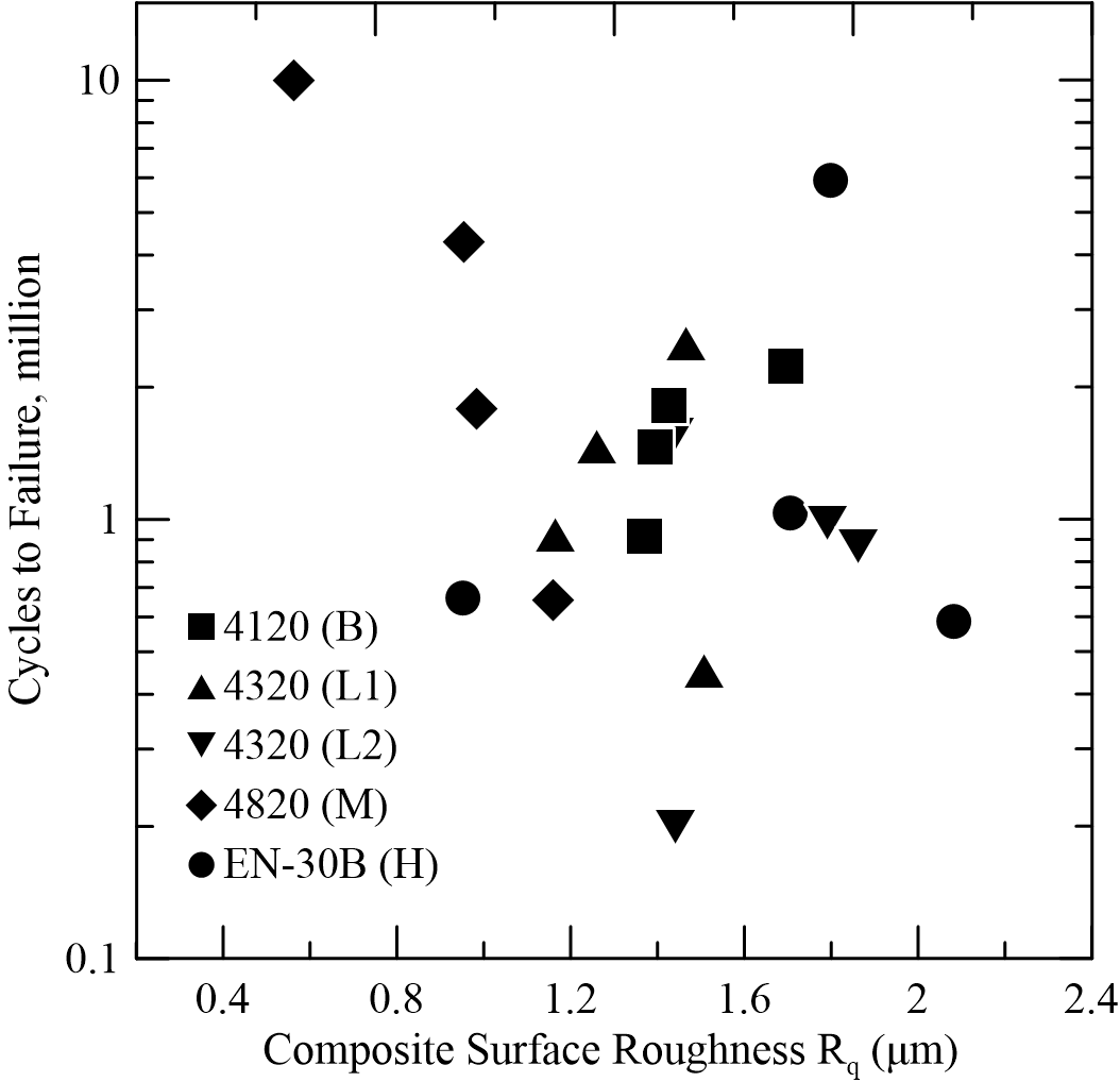
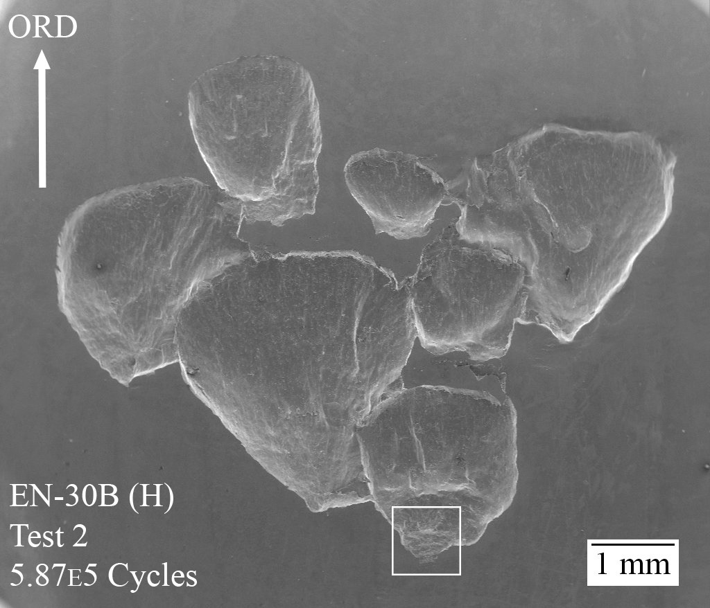
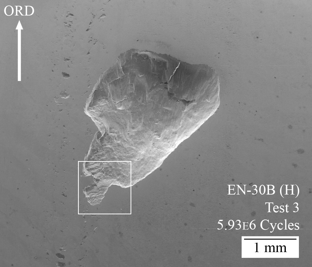
With none of the measured variables showing a strong relationship with fatigue life, the focus of the research shifted to a new proposal: identifying the differences between short-life failures and long-life failures. The failures of two separate tests were selected for comparison. Both tests were performed on EN-30B (H) specimens, and all measured variables were fairly similar. The primary difference between the tests was the life cycle, which differed by an order of magnitude: the short-life test failed after roughly 587,000 cycles, whereas the long-life test failed after roughly 5.93 million cycles.
Images of the macropits show very distinct differences. The low-life specimen failed with a large macropit which seemed to be made up of several smaller macropits, initiating at different points which formed the classic delta shape. The long-life specimen developed a much smaller macropit which initiated along a line of micropitting which was outside the center of the wear track, and then shifted towards the center of the wear track as it grew.
The initiation points of these macropits also show several differences. The short-life macropit has a shallow entrance angle which expanded outward as it propagated in the over-rolling direction, in the classis delta shape. This is typical of a surface-initiated failure. The long-life initiation point was very small and propagated at a steeper angle, as indicated by the tall walls. These characteristics are more typical of a sub-surface initiation.
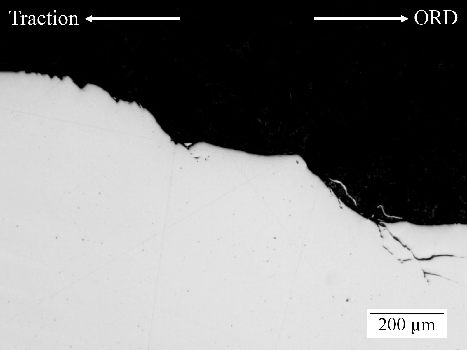
To further investigate these difference, the macropits were sectioned through the centerlines, polished, and observed under a light-optical microscope. These sectional images show that the cracks grew in very different ways. The short-life macropit shows a crack that grows at a steady angle into the material; this crack branches at several points, allowing another crack to grow parallel to the surface, eventually leading to material removal. This explains the jagged appearance at the initiation point, as the crack is concurrently growing deeper into the material while also allowing a flat plane of material to break free. The long-life macropit shows a steep entry angle which connects to a crack which seems to grow against the over-rolling direction. Cracks generally grow in the over-rolling direction, so this suggests that a crack existed sub-surface prior to the development of the macropit.
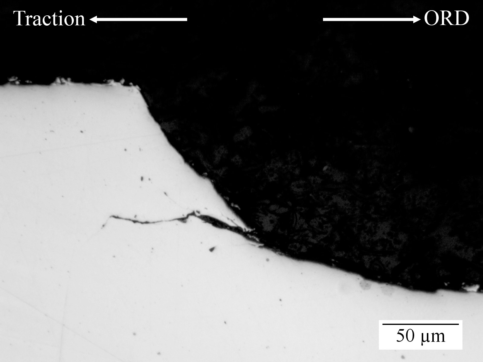
With these images, it was proposed that one of the major differences between short-life and long-life failures under rolling-sliding contact fatigue is the initiation: macropits develop quicker under circumstances which allow surface initiation. The evidence suggests that sub-surface cracking may initiate, but it will grow parallel to the surface and not develop a macropit until a separate crack initiates at the surface and grows until it connects with the sub-surface cracking, allowing a macropit to form. This is supported by evidence which found that sub-surface white-etching areas under RSCF grow at much shallower angles than those under RCF. Future research has been advised to emphasize better control of the specimen surface to study the effects of several variables on initiation of cracks on the surface.
The full text is now accessible through ProQuest, provided by the Colorado School of Mines.