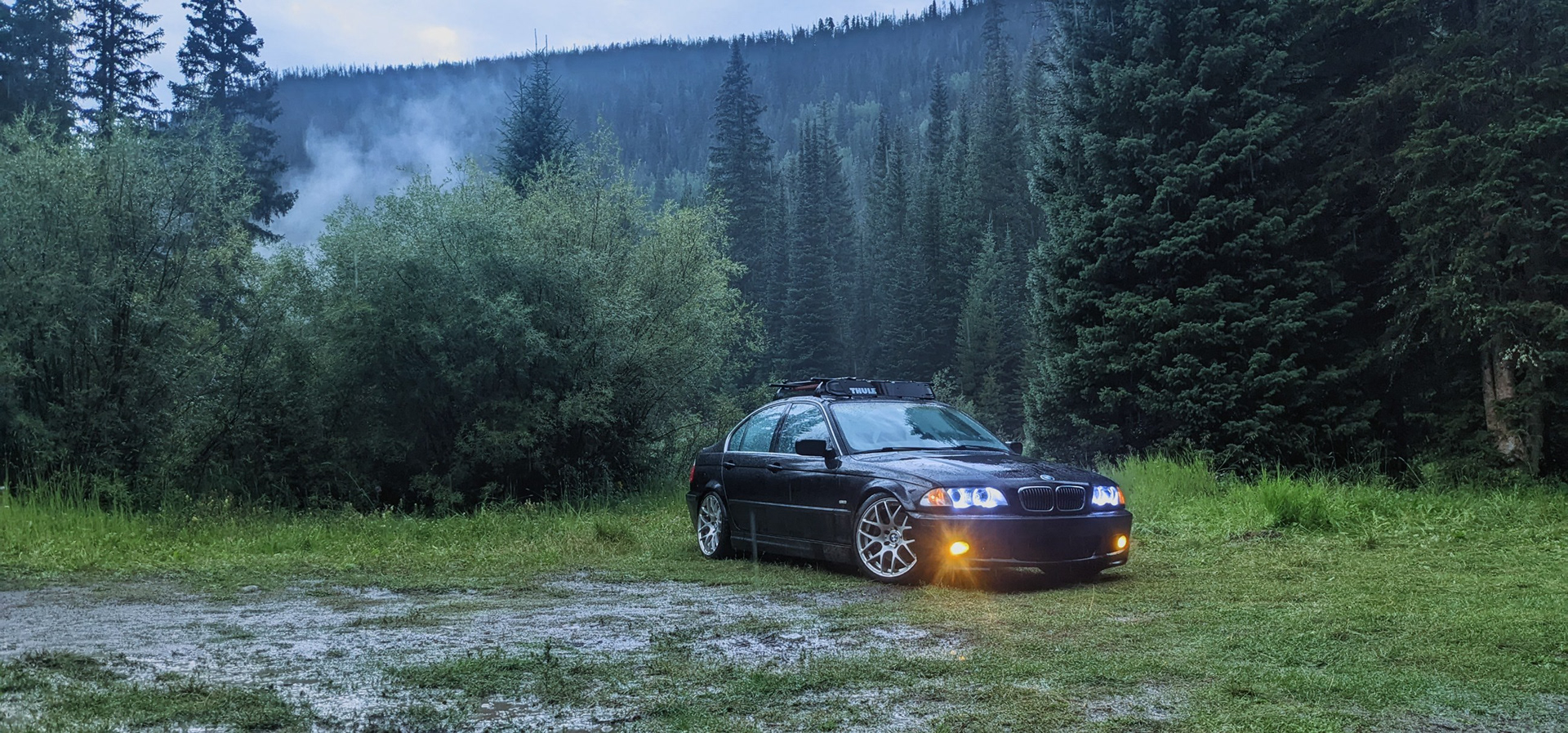
In August 2022, I decided to meet some friends in Winter Park to go camping. I've enjoyed camping since I started back in the Boy Scouts, and I had all the gear that I needed for camping trips far more treacherous than basic car camping. The one piece of gear that I did not have was a proper vehicle: I resorted to using my lowered BMW 3-Series, which made for some amazing pictures, but ultimately proved to be problematic. The cratered dirt roads and protruding rocks were too damaging to the car for me to accept.
Throughout the winter, I decided to part ways with my 7-Series and started looking at my options for a proper camping vehicle. Several options were given serious consideration, but I ultimately decided to buy a BMW E53 X5, the first generation of the SUV which is still popular today. I settled on this option because it had good ground clearance, all-wheel drive, and (most importantly) it shared a similar architecture as my E46 3-Series, which would make it easier to work on. After browsing through listings, I finally found two which fit my requirements and budget: both of them were silver, 3.0i inline-6 (same M54 engine as the E46 3-Series), and a rare 5-speed manual transmission. I test drove one of them and had a friend take a look at the other; unfortunately, both of the deals fell through.
I began my search over again and came across some listings for old Volvo XC70s which re-sparked an idea I had come up with the year prior: to build a gravel wagon - the automotive equivalent of a gravel bike. Good ground clearance and all-wheel drive for getting around, plenty of cargo space, and long enough to sleep inside. The Volvo XC70 fits all of the criteria, with the exception that it has the reputation and eye appeal of a suburban soccer mom daily. Despite that reputation, I dove in to learn everything I could about the potential platform. I determined that the best example for the project base would be a facelifted P2 generation (model years 2005-2007). Although this was built under Ford ownership, it as a fully Swedish design (the following P3 generation is built on a Ford Mondeo chassis), and the facelifted variants have a slightly more robust transmission. Better yet, there is an existing albeit small aftermarket of parts available for making the chassis more offroad-capable.
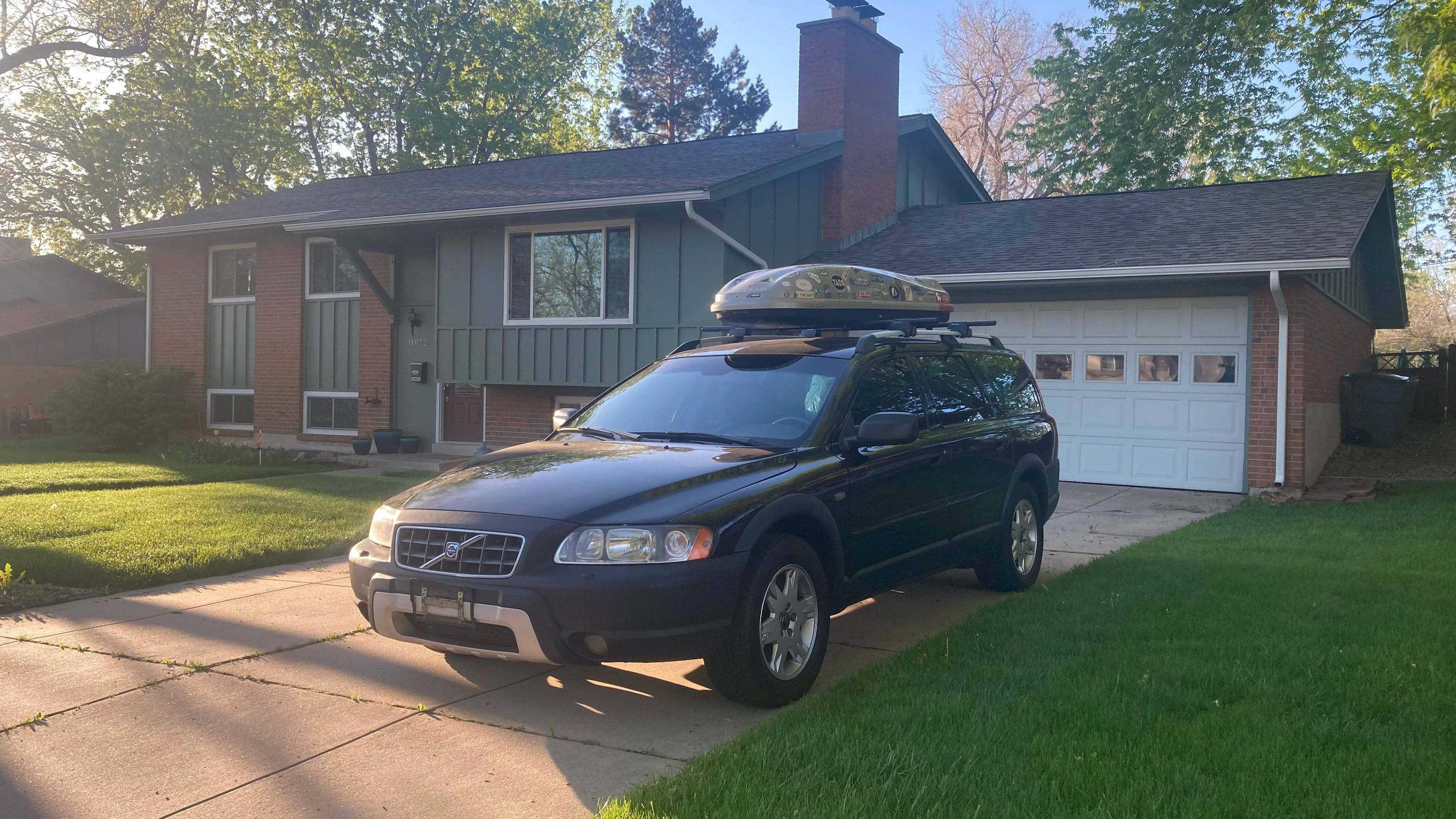
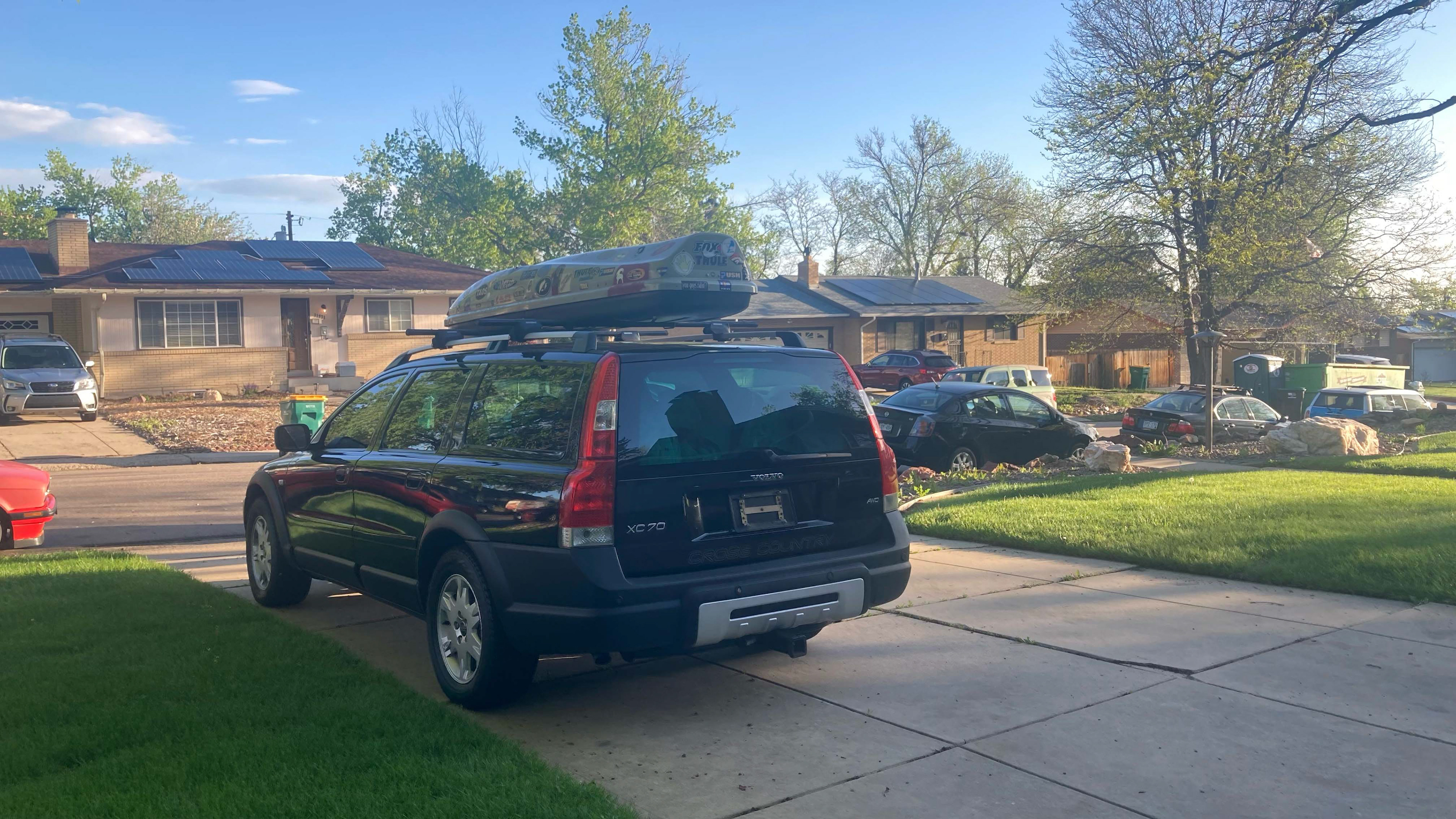
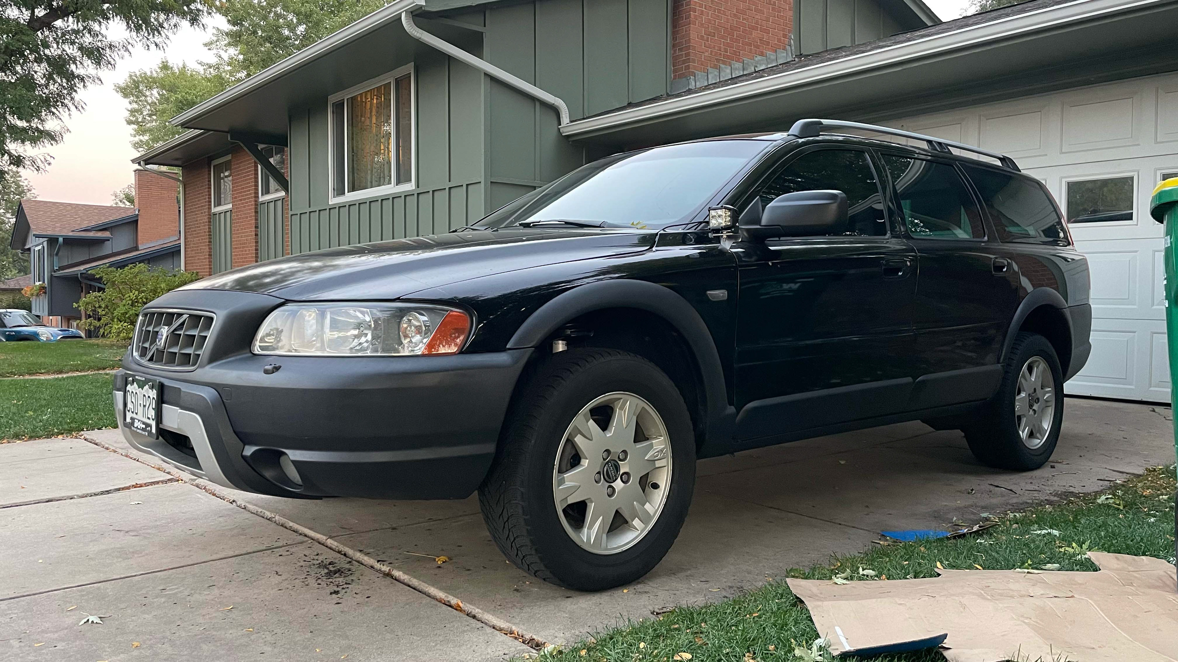
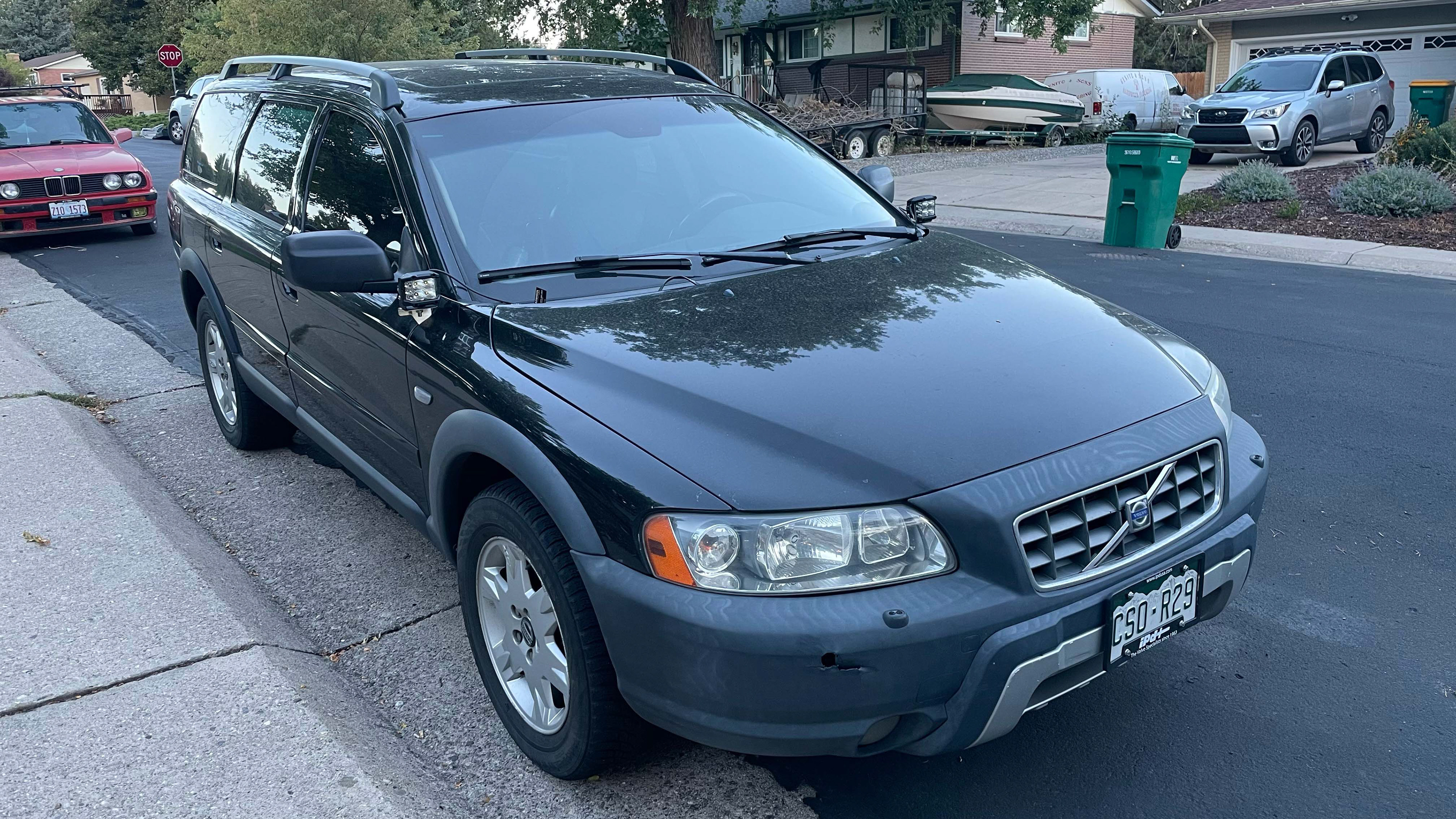
With my research done, I dove back into the listings. After searching through dozens of options, I finally settled on one which looked like the best: a 2006 single-owner which was left stock and fully serviced at the local dealership. Within a week of selling my 7-Series, I had a new-to-me Volvo XC70 on my driveway.
BASIC MAINTENANCE AND UPGRADES
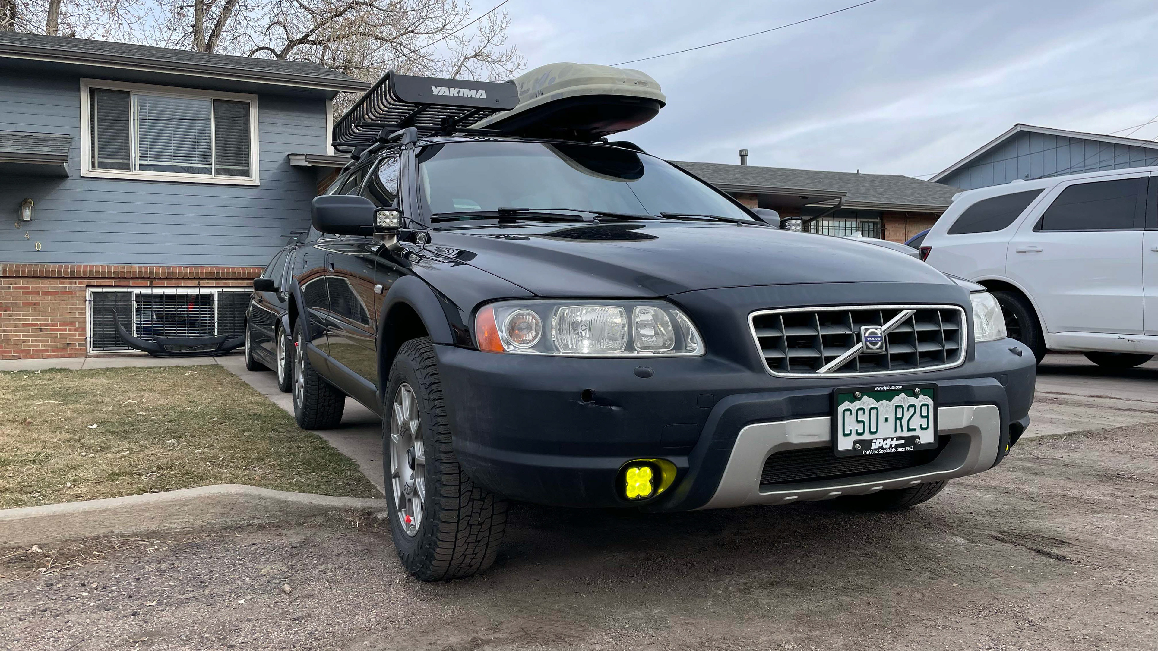
The first steps after purchasing the car were to iron out all of the basics and do some simple bolt-on modifications. Oil change, air filter, and fuel filter were the first steps. Following the basics, I upgraded a handful of the lights to LEDs to give it a more modern look. The brakes were replaced with new rotors, ceramic pads for smoother and more heat-resistant performance, and stainless steel brake hoses which are more rigid and bulletproof than the stock rubber hoses. The final step before winter approached was to replace the stock plastic engine splashguard with a formed aluminum skid plate, which will help protect the vulnerable undersides of the engine and transmission from potential rock strikes. Additional pictures show the car doing some basic camping which was chalked up to baseline performance testing.
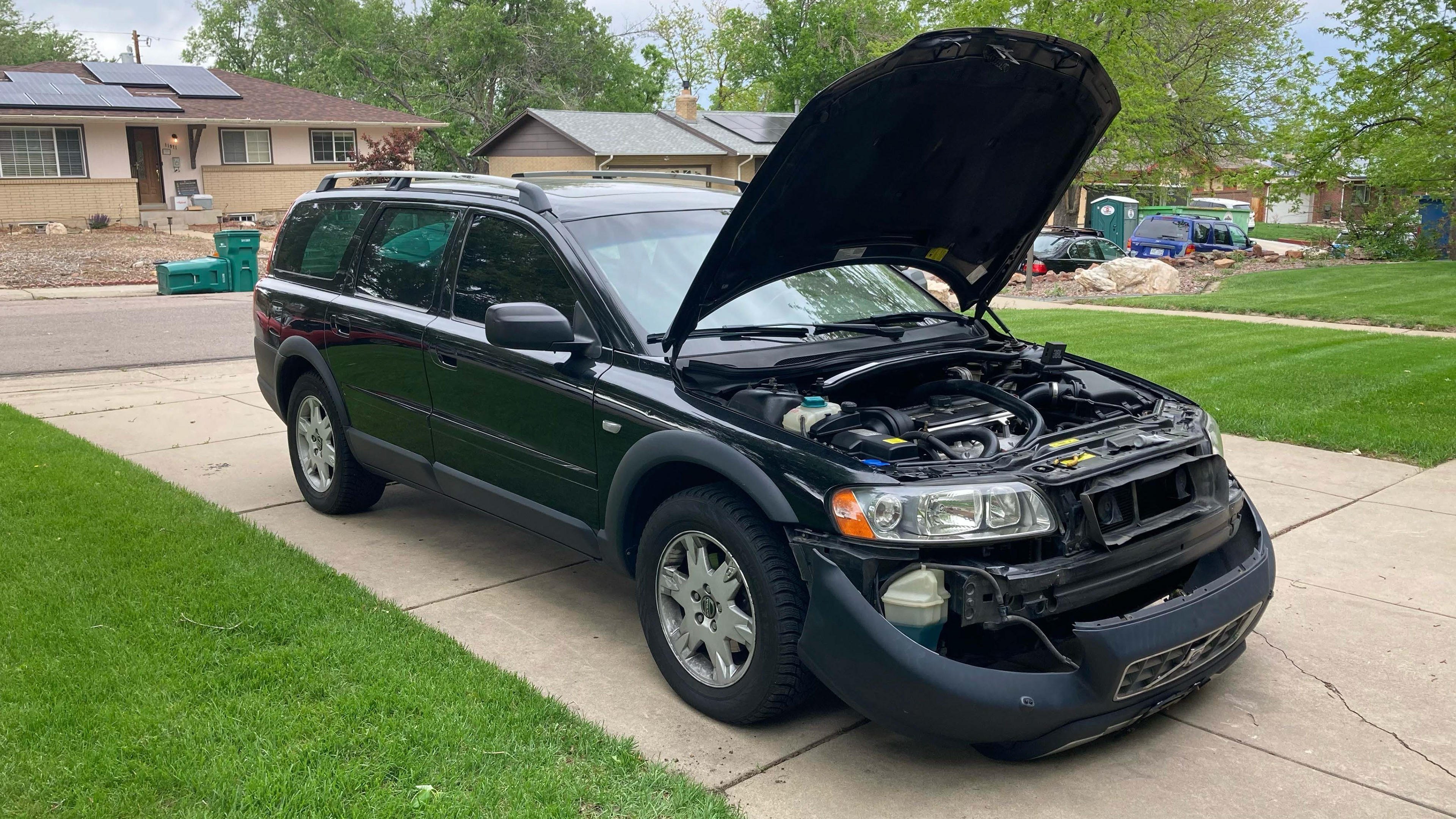
The bumper was removed to pull the headlights and replace standard running bulbs with LEDs.
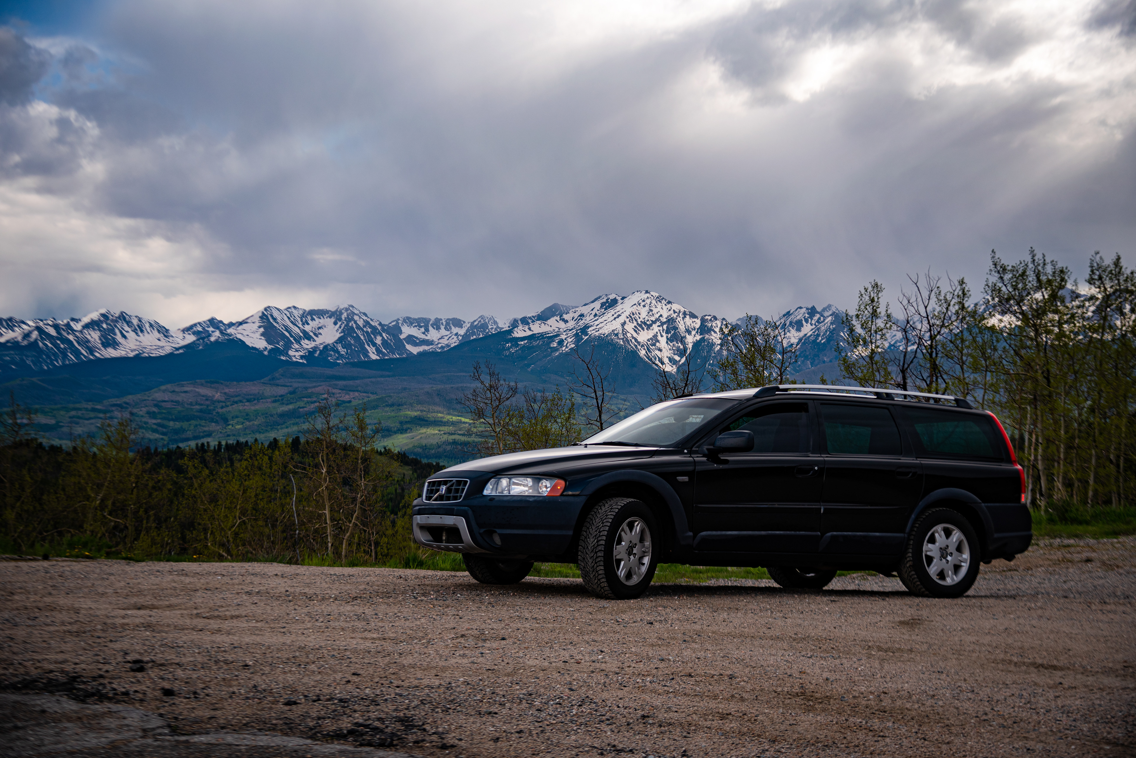
Ute Pass, Colorado
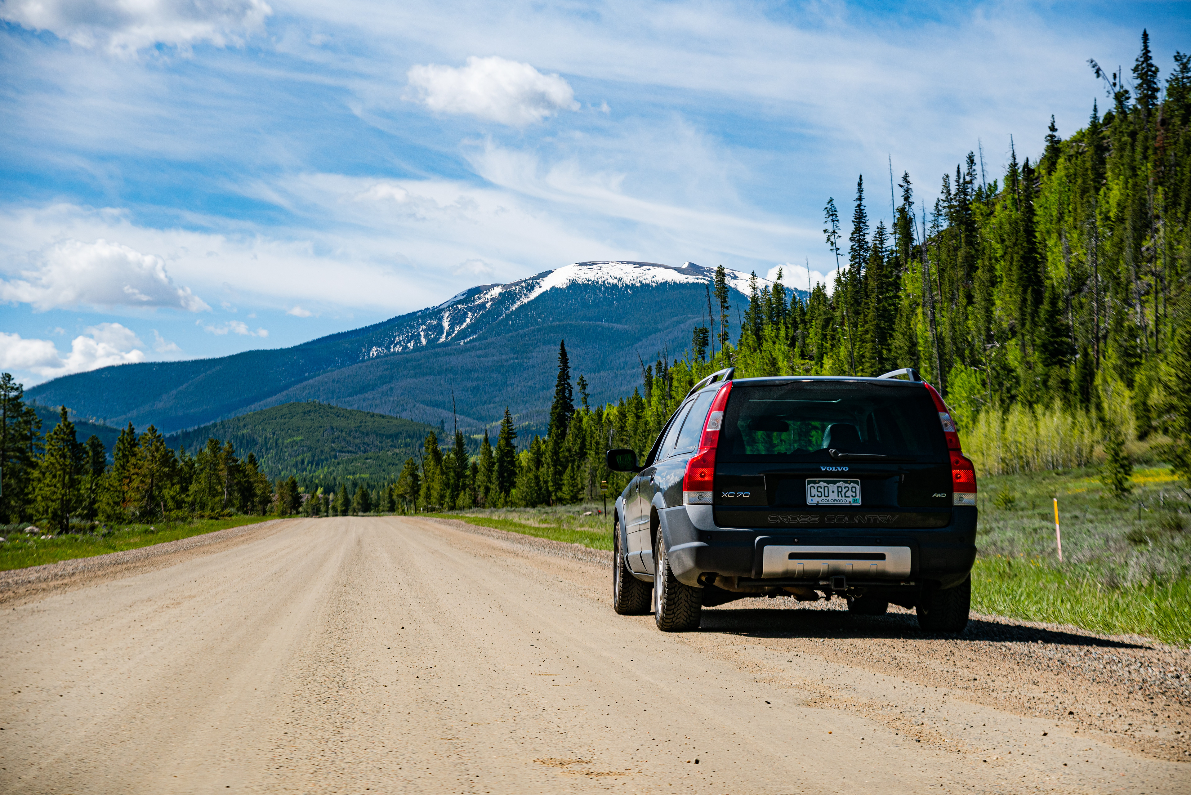
Off Ute Pass, Colorado
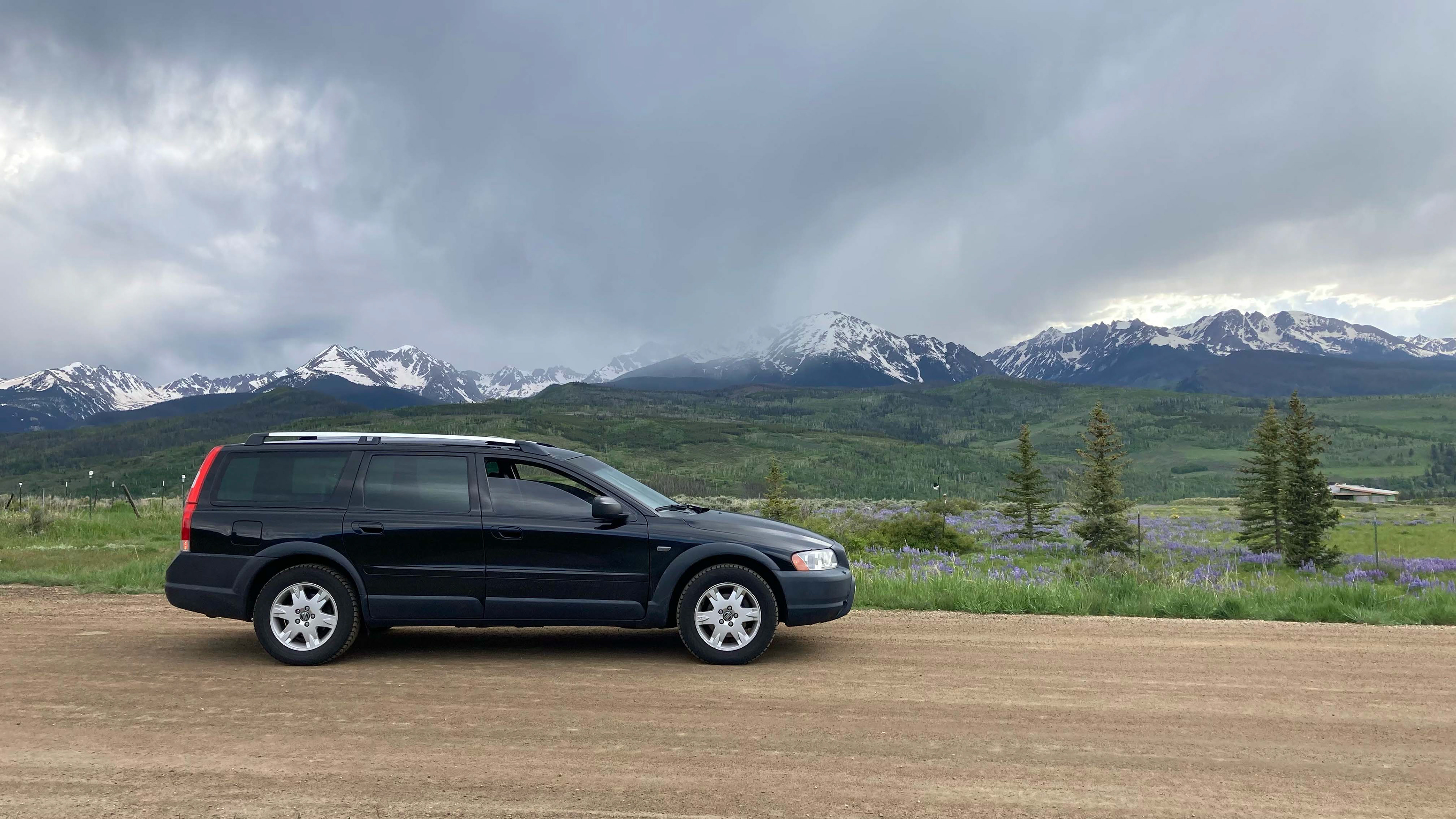
Ute Pass, Colorado
SUSPENSION UPGRADES
The clear choice in upgrading the suspension was to install a lift kit. Luckily, there are two options available for the P2 chassis: a spacer lift and a spring lift. The spacer lift wedges blocks between the top of the suspension members and the frame to add height, similar to stilts. The spring lift replaces the stock spring with one that has a heavier spring rate. Although this compromises the smooth ride of the chassis, I decided that this was the best option for two reasons: 1) it will prevent the car from bottoming out in case I find myself in a pack of prerunners, and 2) it is slightly more straightforward to install. The stock P2 rubber suspension bushings are vulcanized to both sleeves and pre-tensioned at the ride height - this provides a very smooth ride by damping out bumps, but makes it difficult to remove suspension components at full extension because the tension is pulling all of the components back towards ride height. The spacer lift would be more straightforward, but would push the components further from ride height, making installation (and regular service projects down the road) a lot more difficult. After deciding on the spring lift, I was upset to see that they were only sold in batches, and the prior batch had sold out with no target production date set for the next batch. To my luck, I found somebody local who was selling their old set right as I was purchasing my XC70, so I went and picked up the springs.
Despite having the springs in my possession, another year and a half would pass before the lift would be completed. It was important to get a baseline feel for the car so I could feel any need for improvement, and it also allowed me to iron out the basic maintenance as well as a stubborn sheared suspension bolt. The baseline evaluation also proved to be important because the chassis was found to be very prone to body roll; because the lift would raise the center of gravity and accentuate this trait, I decided to add upgraded anti-roll bars to the list of upgrades.
Work finally began in the Fall of 2024 and lasted several weeks due to my apprehension to use a spring compressor and the decision to replace some hardware which was found to be worn out and prone to failure with the increased forces. Apart from the dangers of the spring compressor, the spring lift turned out to be fairly straightforward; the front and rear spring/damper units are fully contained, so they hold the same uncompressed height as stock and are very easy to swap in/out (the higher spring rate is what holds the car at a 2" taller ride height than stock).
In order to maintain suspension geometry at the raised ride height, 0.5" spacers were sandwiched between the subframe mounts and the primary frame - this prevents visibly positive camber and excessive wear on the CV axles. These spacers are available from aftermarket sellers, but I found that the product lines were not complete - although they provide all of the spacers for the subframe, they do not provide anything for the brackets which brace the subframes nor the exhaust. After using paper 1:1 templates and 3D-printed prototypes, I finalized a design in CAD and had them laser cut.
The bear of the project turned out to be the front anti-roll bar: the Volvo engineers decided to mount everything to the top of the front subframe, which cleans up the bottom of the vehicle and makes it very easy to assemble at the factory. Unfortunately, this means that the subframe must be dropped significantly to allow enough clearance to wiggle the old bar out and install the new bar. After nearly dropping the engine on the ground, I supported it from the top, lowered the subframe, and wrestled to replace the bar until my knuckles were sufficiently bloody to call it a true project.
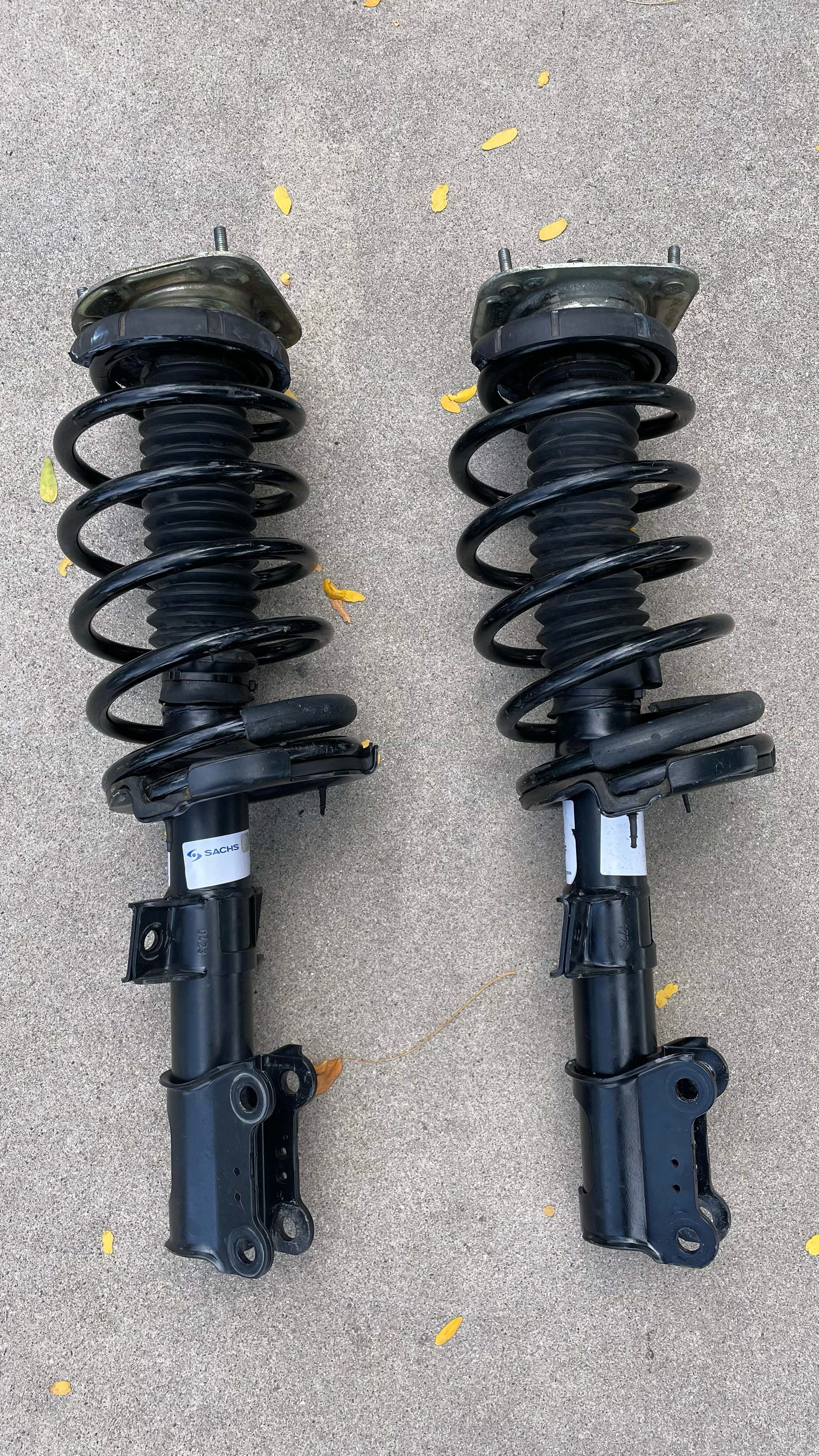
Front struts with new springs.
Right Rear
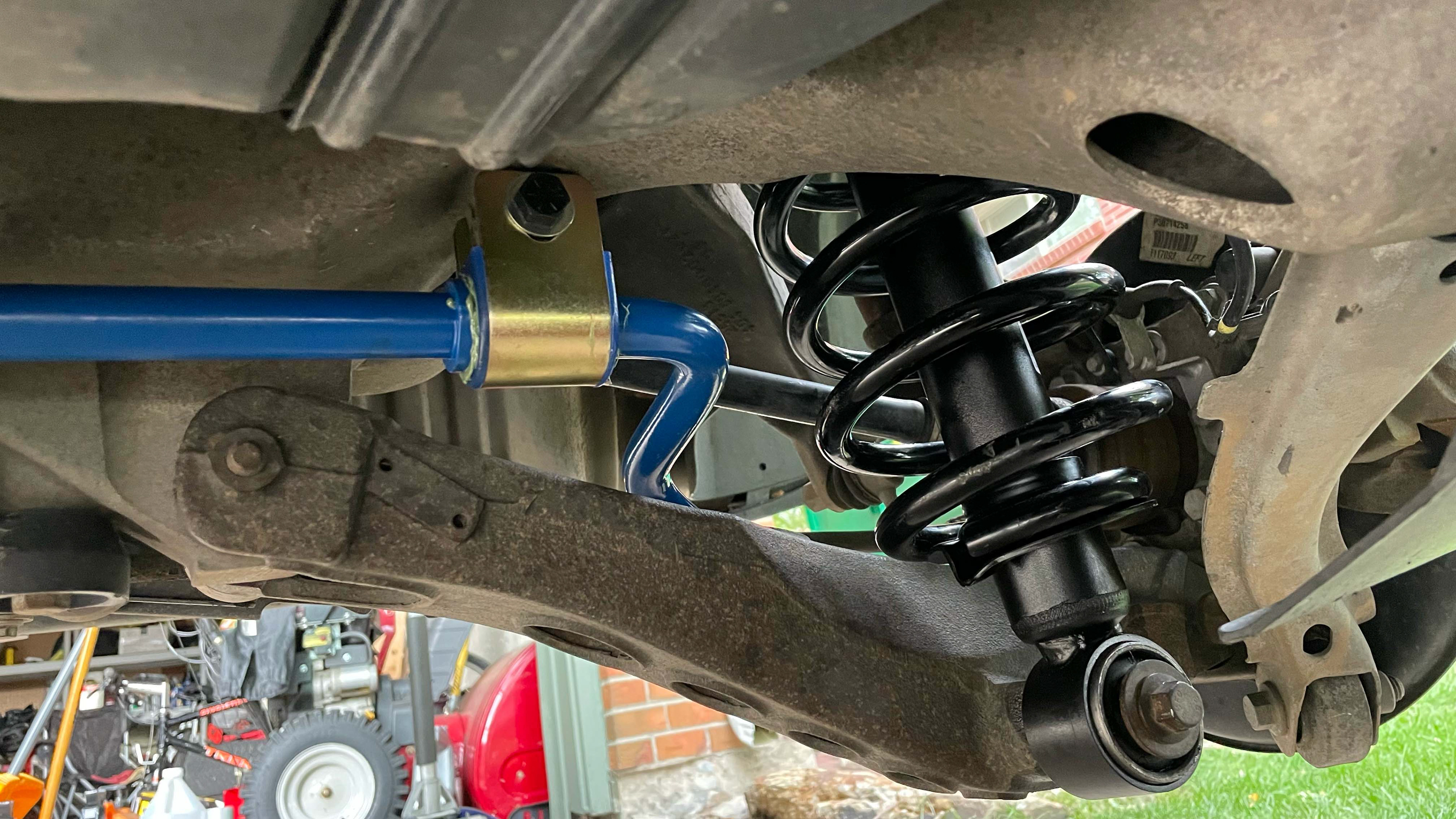
Left Rear
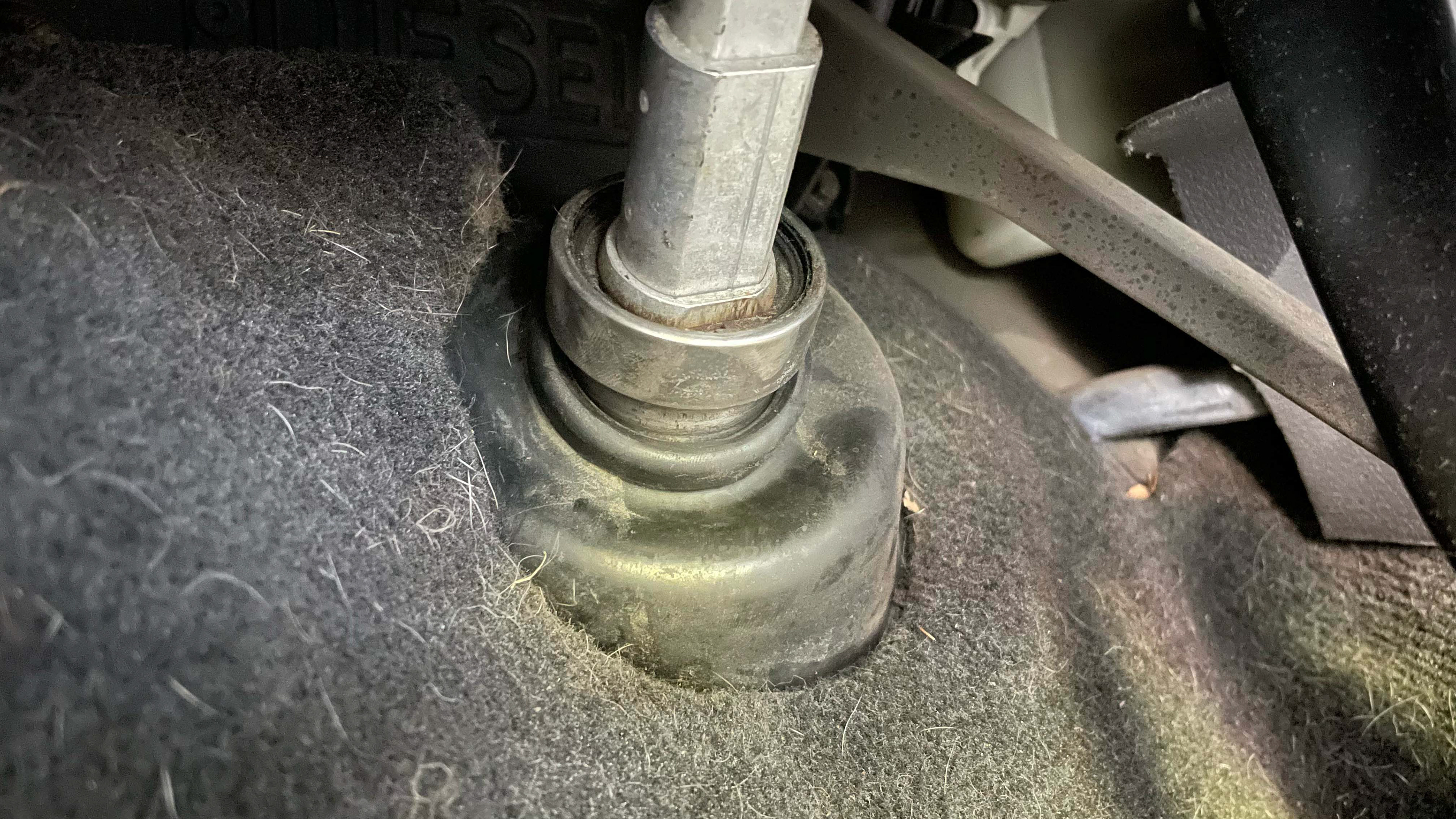
Slipped bearing between the steering shaft and rubber bellows.
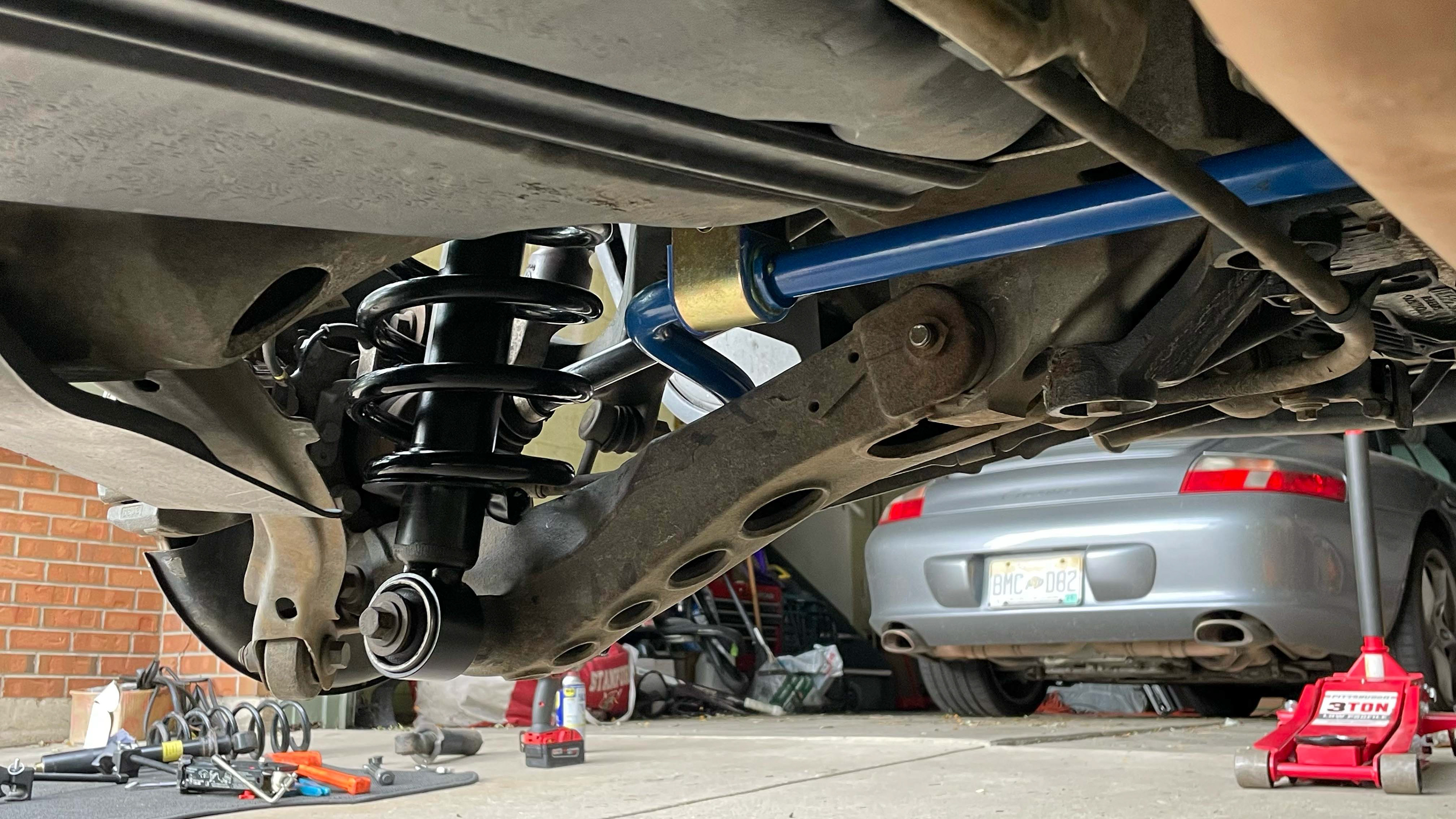
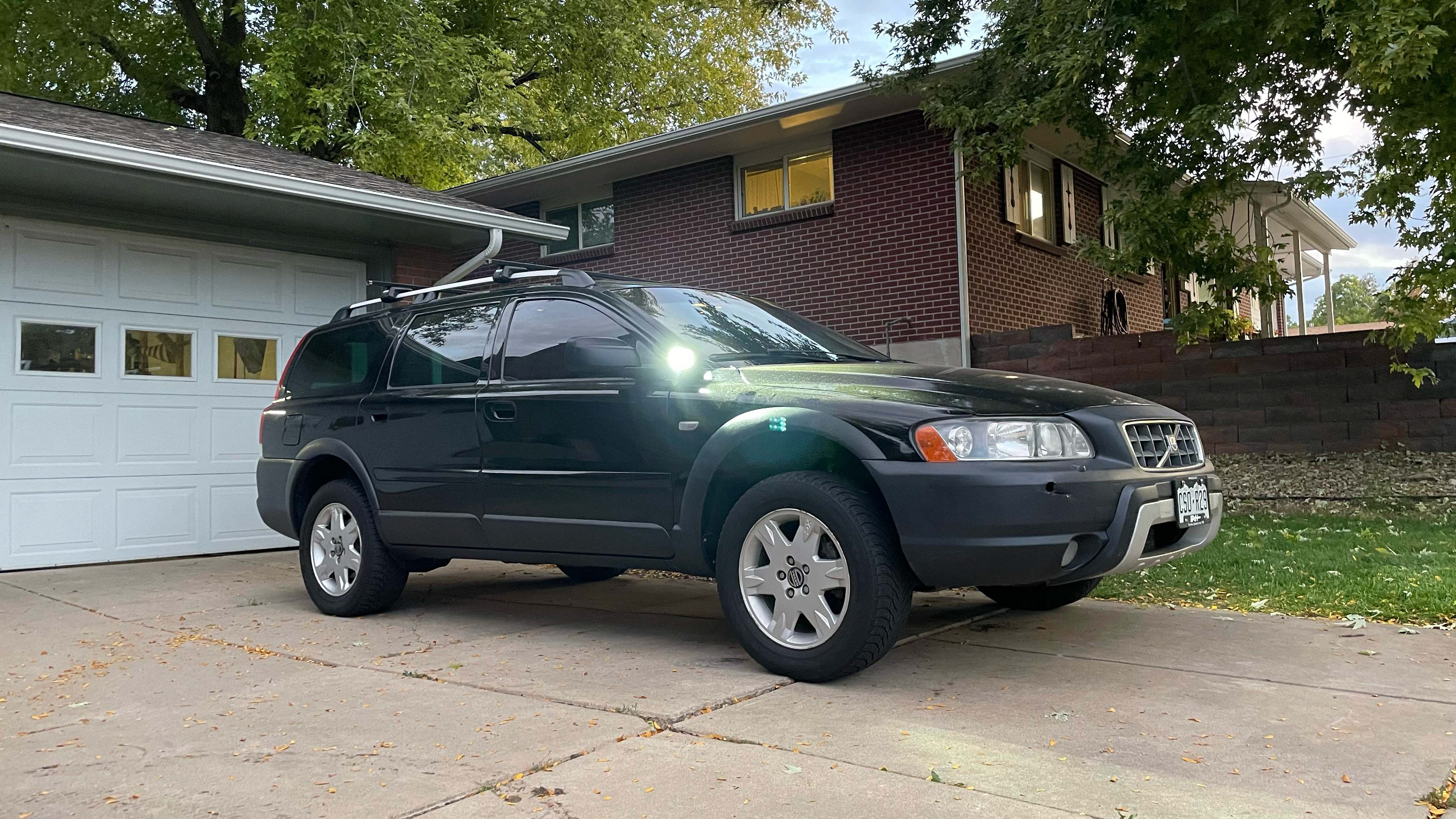
Completed Lift
The final step of the suspension project was upgrading the wheel/tire setup. I decided the best tire option would be the Falken Wildpeak Trail - this offers great all-terrain performance, but only has a mildly-aggressive tread pattern which retains similar fuel economy and wear rates as all-season tires. For the wheel option, I selected the Sparco Terra 16" for the sole reason that they look really cool, albeit not in production anymore. By a stroke of luck, I found another local Volvo enthusiast selling a set of 16" Sparco Terras with a compatible bolt pattern wrapped in almost-new Falken Wildpeak Trail tires (he was unbuilding his Volvo after an engine failure to fund other projects). With that, the suspension system was all wrapped up.
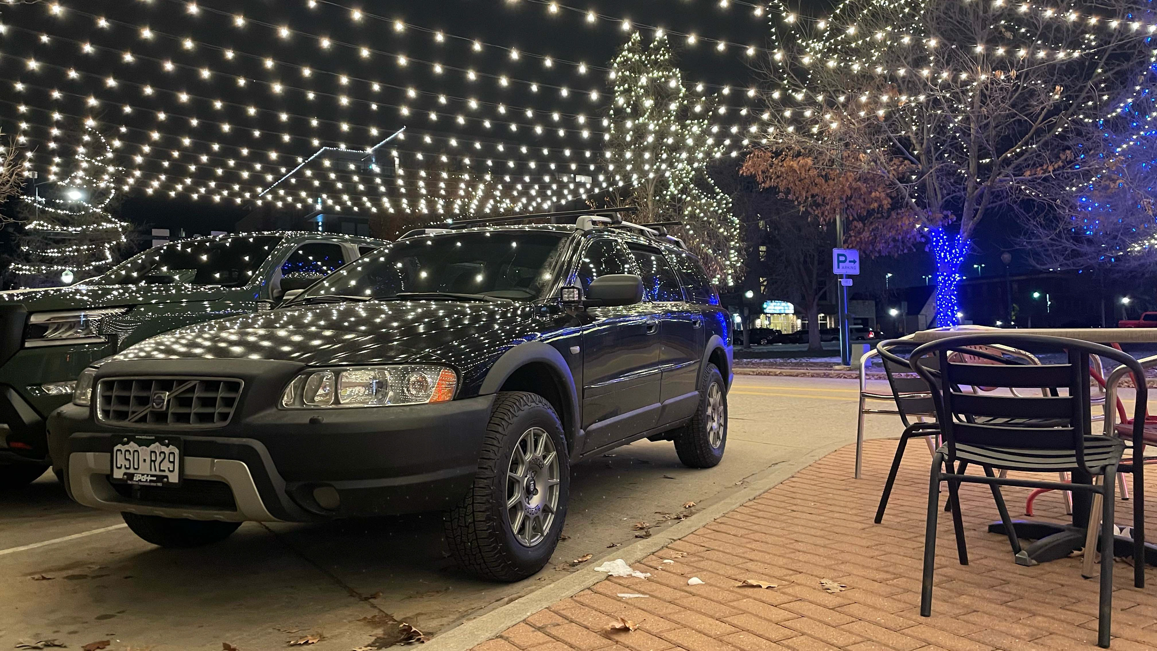
Lifted and sitting on the new wheel/tire setup.
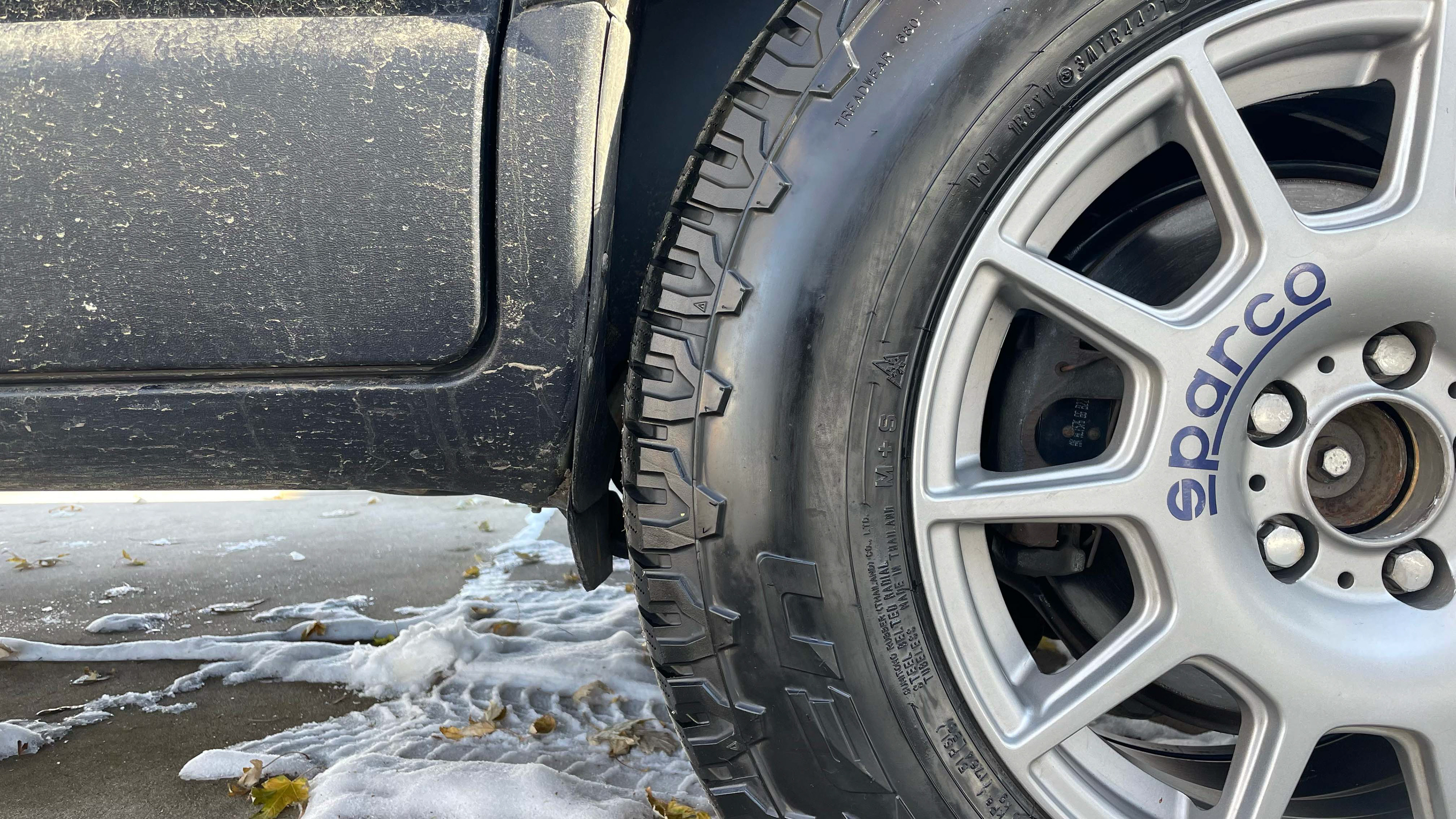
Clearance between the rear wheel and the front of the wheel arch.
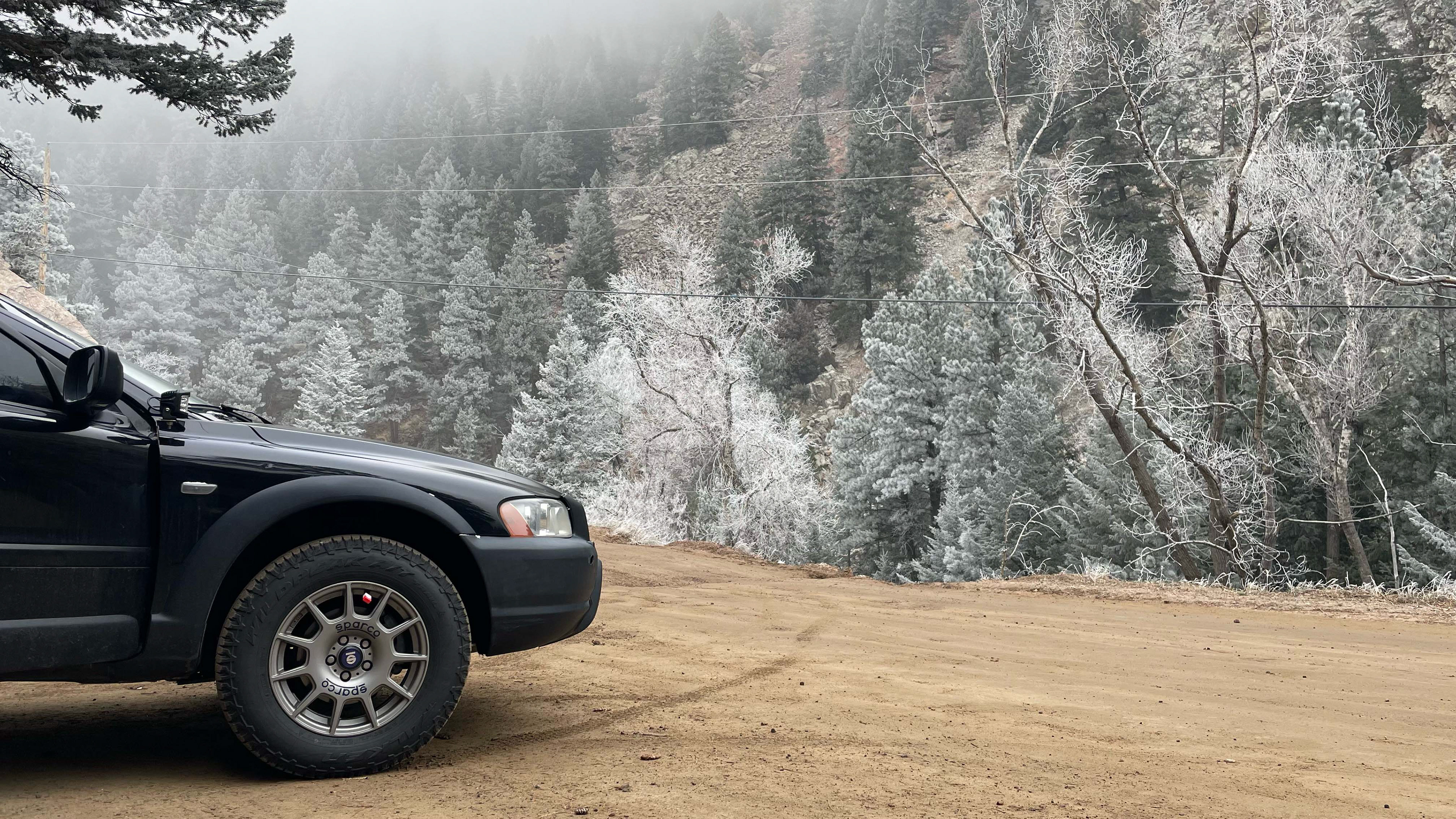
Testing out the tires at El Dorado Canyon State Park.
LIGHTING UPGRADES
Apart from the suspension, one of the major upgrades I wanted to implement was an improved lighting setup. The stock halogen lights are fine for most use-cases, but dark mountain roads and heavy storms unveiled a desire for more. After browsing my options, I decided to add auxiliary flood lights with side shooters for tight corners and dark camp sites; auxiliary spot lights for visibility on longer stretches of dark roads; and upgrade the halogen fog lights to amber LED pods for improved brightness and contrast.
FLOOD LIGHTS
The auxiliary flood lights were the easiest first addition. I selected pod lights with a flood pattern and additional side-shooter lights which would be useful for shining into tight switchback corners. The best mounting location for these lights would be near the A-pillars, where the lights are shielded from the driver's line of sight while offering a good vantage point to light up both the front of the car as well as the sides. The major hurdle was the lack of any good mounting options - other chassis like Toyotas, Jeeps, and Subarus have plenty of aftermarket options to mount A-pillar pod lights, but none for Volvos. I decided to design my own mounts and found a way to wedge them between the front doors and the fender. I am not a fan of drilling new holes unless absolutely necessary, so I decided to fasten them by using a hemmed tab to grip the fender and sharing an existing bolt which fastens the fender to the frame. I did some preliminary measurements, designed a bent sheet metal part in CAD, and sent it out for fabrication. The vendor was not able to create hemmed edges, so I bent the tab to 135deg and closed it in a bench vise. The pod lights were fastened to the mounts and wired directly to the battery - this poses the potential to drain the battery if they are turned on while the engine is not running, but allows the user to light up a campsite without needing to turn the car on. The second revision of these mounts are currently in development to address several minor shortcomings of the initial design.
FOG LIGHTS
With the flood lights installed, the next item to tackle was the fog lights. My fog lights were now working when I bought the car, which was due to the housings being coated in dirt and the light mounts damaged. I debated simply upgrading to LED bulbs, but ultimately decided that a full upgrade would be better. Initial measurements showed that a 3" square LED pod would fit tightly in the bumper cutouts. I found an option that I liked which has a lens-refracted fog-light pattern, amber lenses, and orange backlights for better visibility to other vehicles. Other offroad XC70 builds have installed LED pod fog lights; however, they generally drill straight into the bumper or frame rails. Although this works, it is a clunky solution, so I decided to go the hard route: designing new housings for the LED pods.
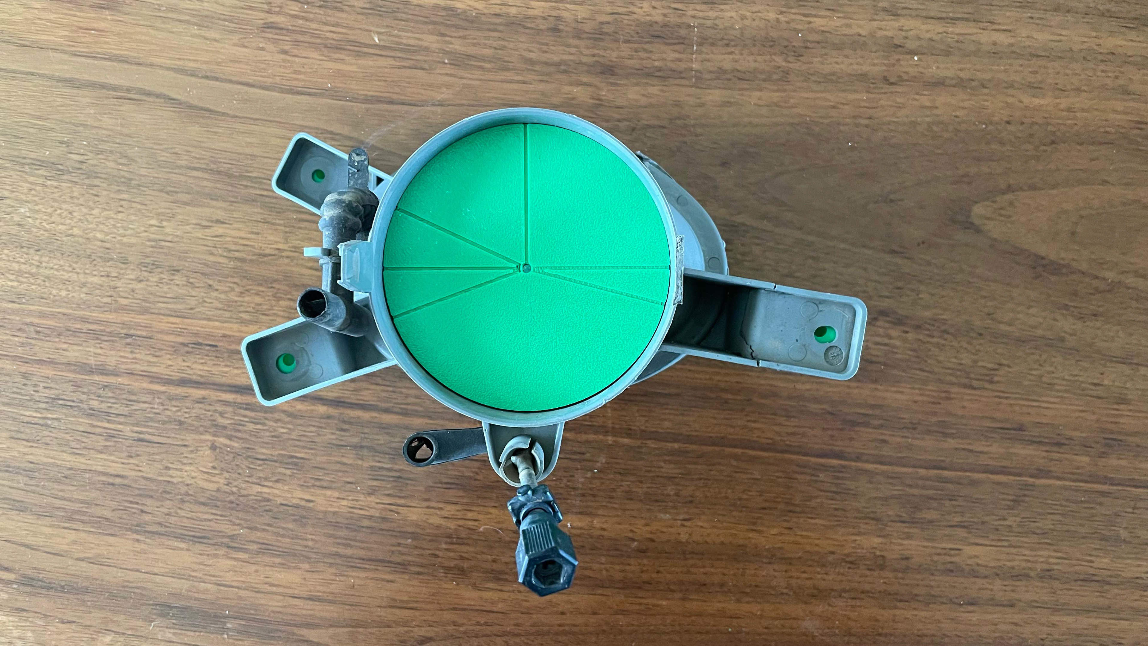
The first step in this was to remove the original fog light housings to take measurements. They are a particularly challenging part because the mounting tabs sit on different planes and different angles. I took measurements of each tab as best as I could and used several iterations of 3D-printed tools to visually check the alignment until I had high confidence of the mounting planes of each tab.
Tool 1 used for estimating the angles to vertical that each mounting tab sat on.
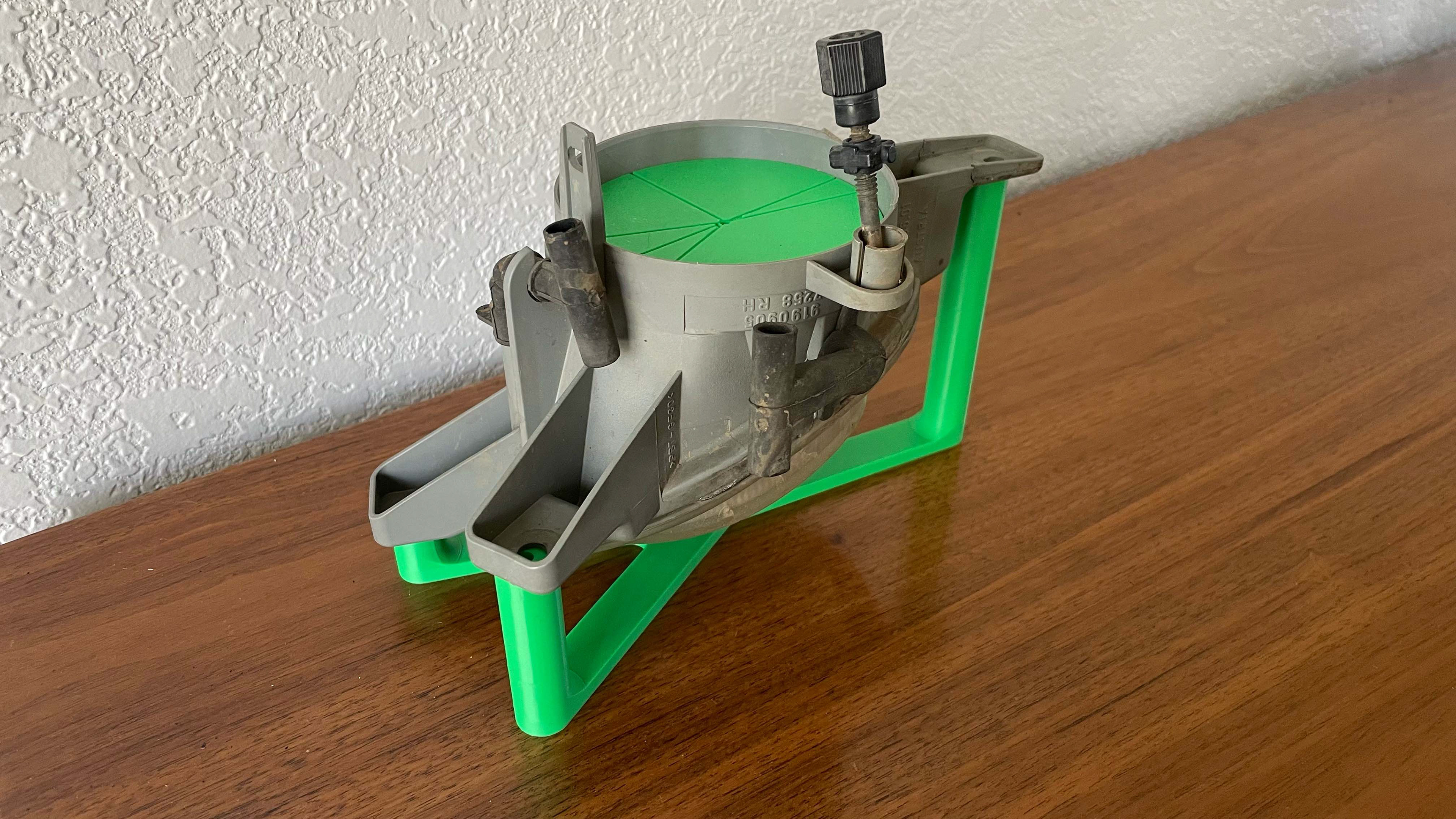
Tool 2 used for determining the horizontal plane of each mounting tab.
With the mounting planes determined, the housings were designed around the pod lights which I selected (although most designs are very similar and these could be used on other units as well). I took some rough measurements of the bumper and the available real estate to guide the required cuts to ensure fitment, but it took several iterations before there was a final design which fit well in the space provided and allowed some slots for tools to adjust the aim of the pod. The final design was printed using ASA filament, which is stronger than the standard PLA filament used for prototyping and also very resistant to heat, moisture, and UV rays, all of which the housings would be exposed to in their operating environment.
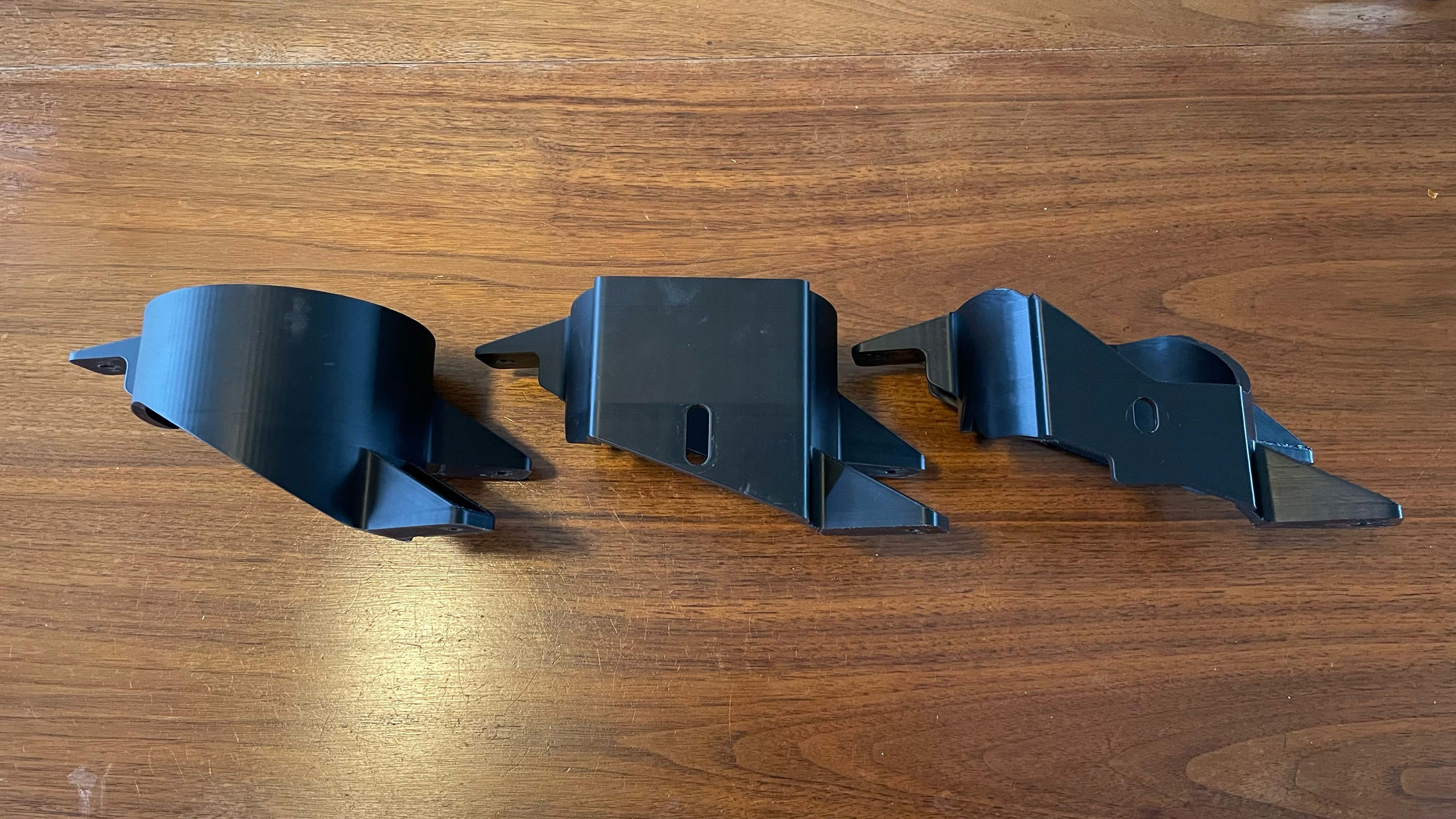
Evolution of the housing (initial on left, final on right).
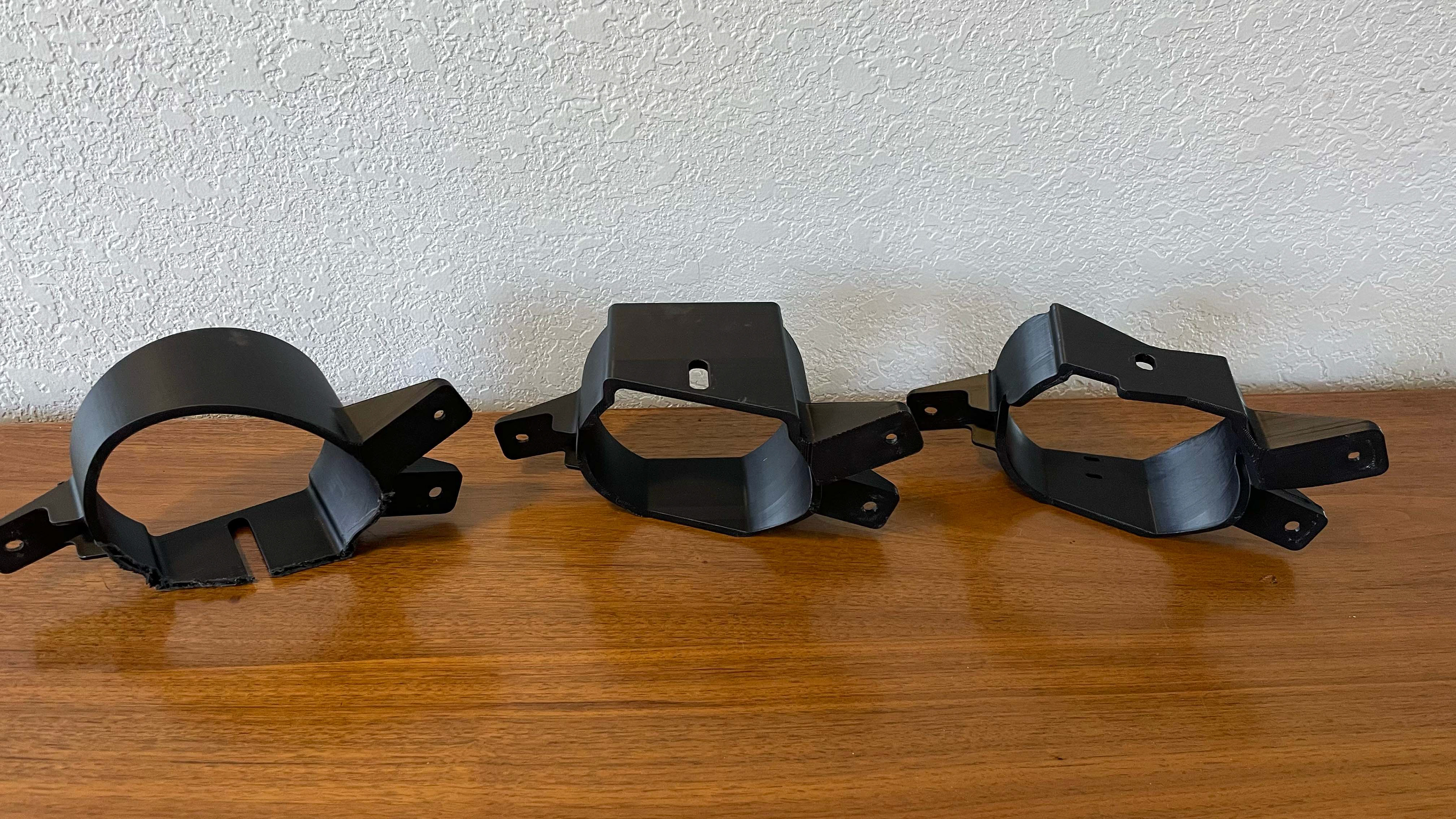
Evolution of the housing (initial on left, final on right).
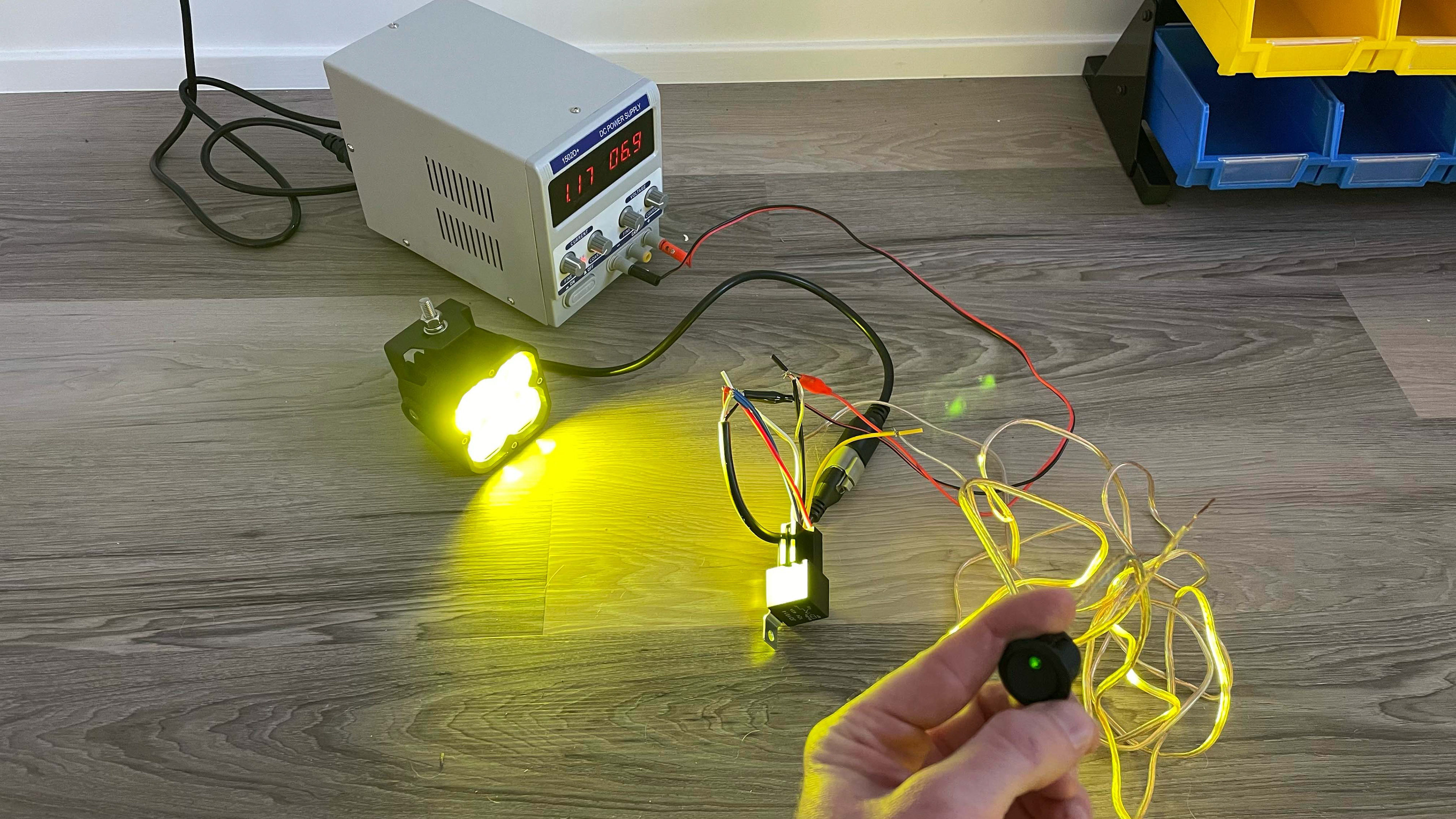
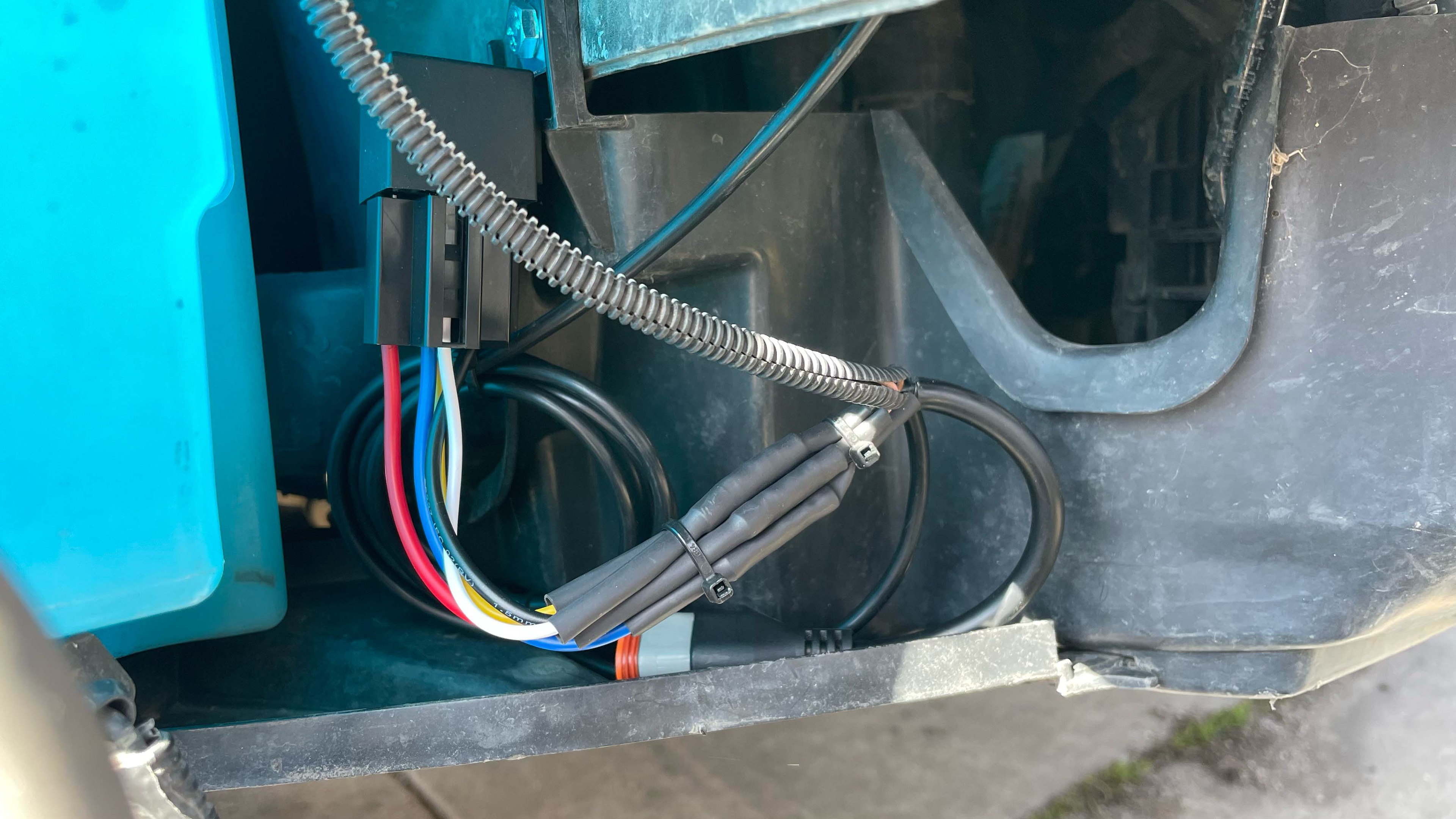
With the housing design completed, I dove into the next barrier: the wiring. The lights I selected have a three-wire pigtail connector: one for ground, one for fog lamp power, and one for backlight power. This meant that the stock two-wire setup would not allow me to use the backlight feature. I first decided how I wanted the lights to operate: the stock fog light switch would power the lights, and an auxiliary switch would alternate between the backlight and the fog lamp. In order to convert the 2-wire setup to a 3-wire, I used a 5-pin relay as a switch. I developed a basic wiring diagram which allowed the operation I wanted and also kept all of the switches on a low-current system. The stock fog lamp switch gives power to the auxiliary switch; the auxiliary switch is used to determine where the power is directed in the relay (backlight or fog lamp); and the relay allows the stock fog lamp wires to power the pod lights. This setup was tested using a 12V power source as well as on the car before the wires were crimped together and sealed with heat shrink.
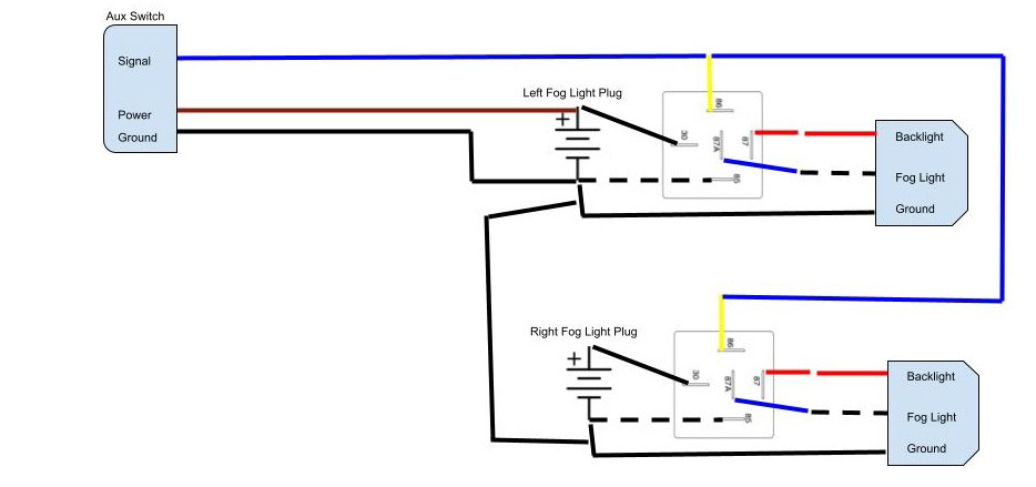
Wiring diagram of the lighting setup.
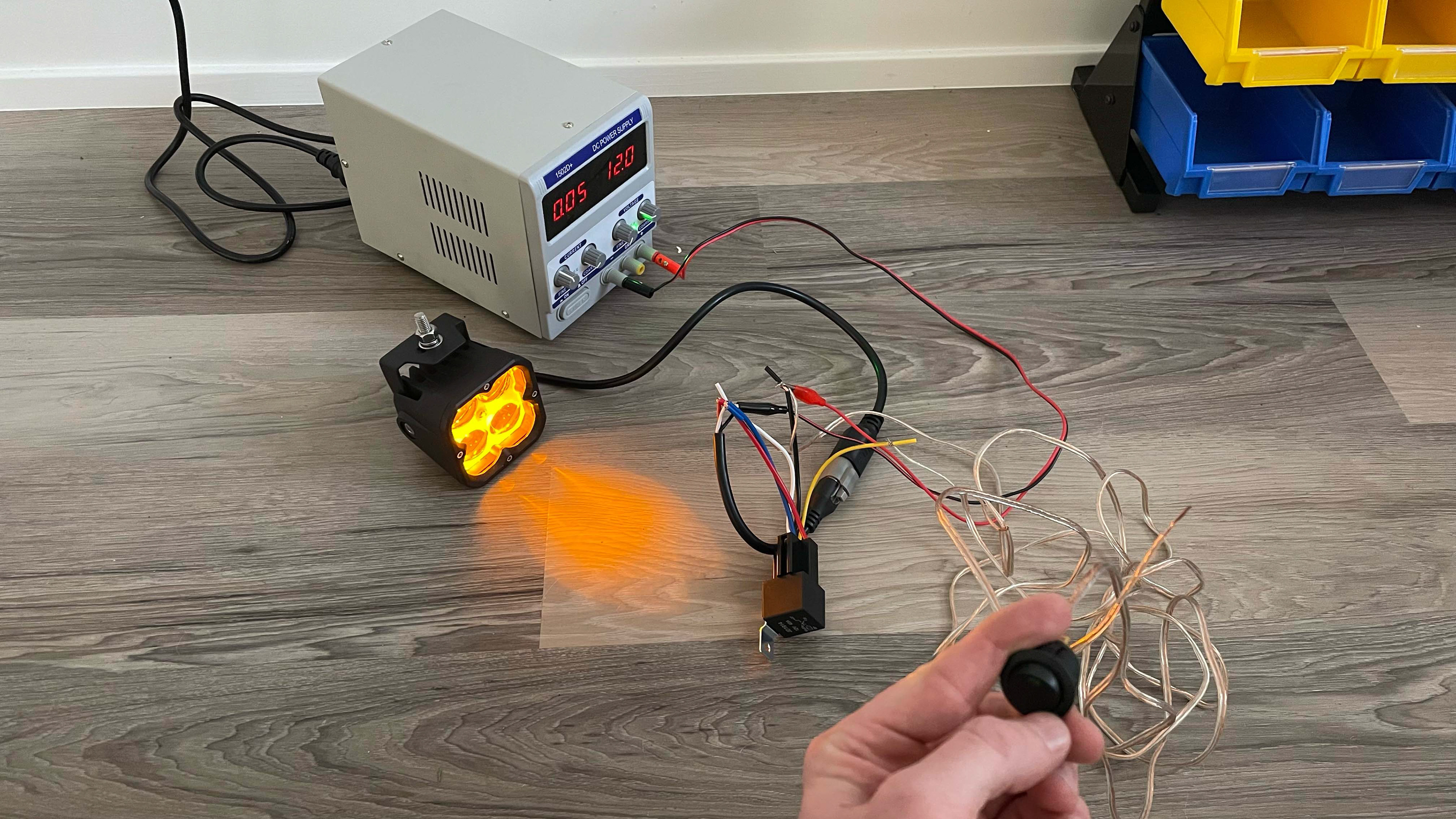
Testing the backlight feature on the bench.
Testing the fog lamp feature on the bench.
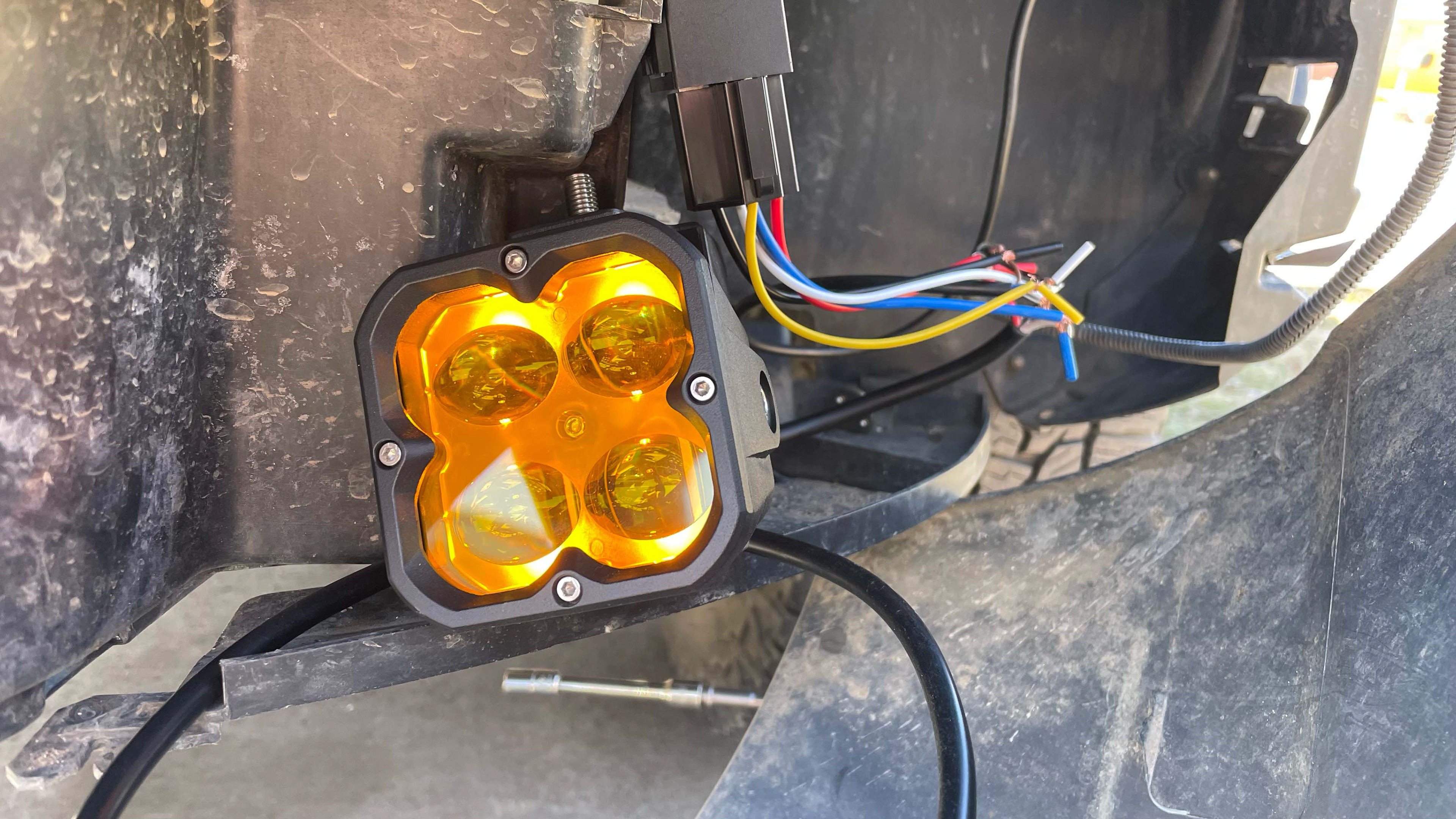
Testing the backlight feature on the car.
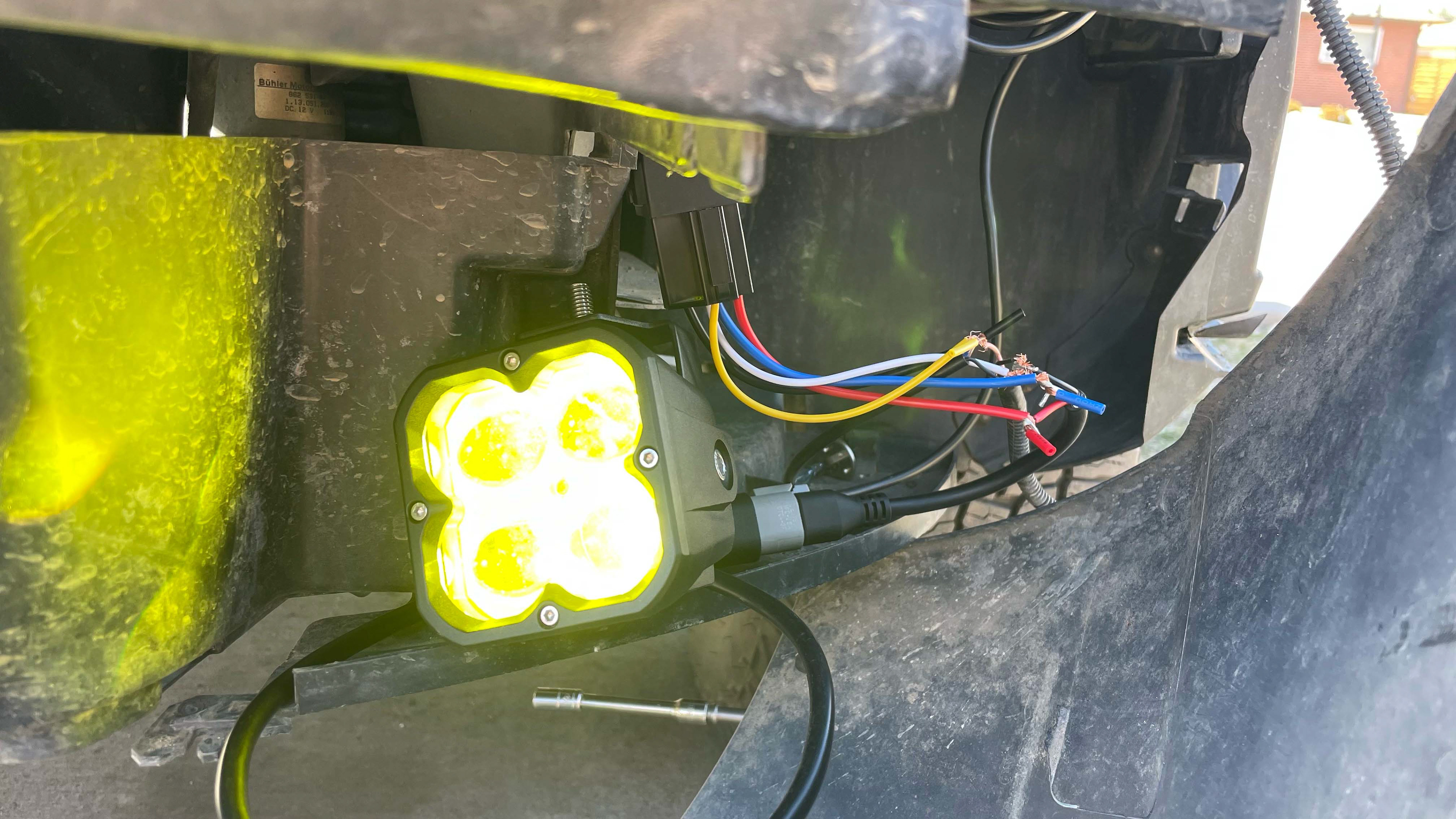
Testing the fog lamp feature on the car.
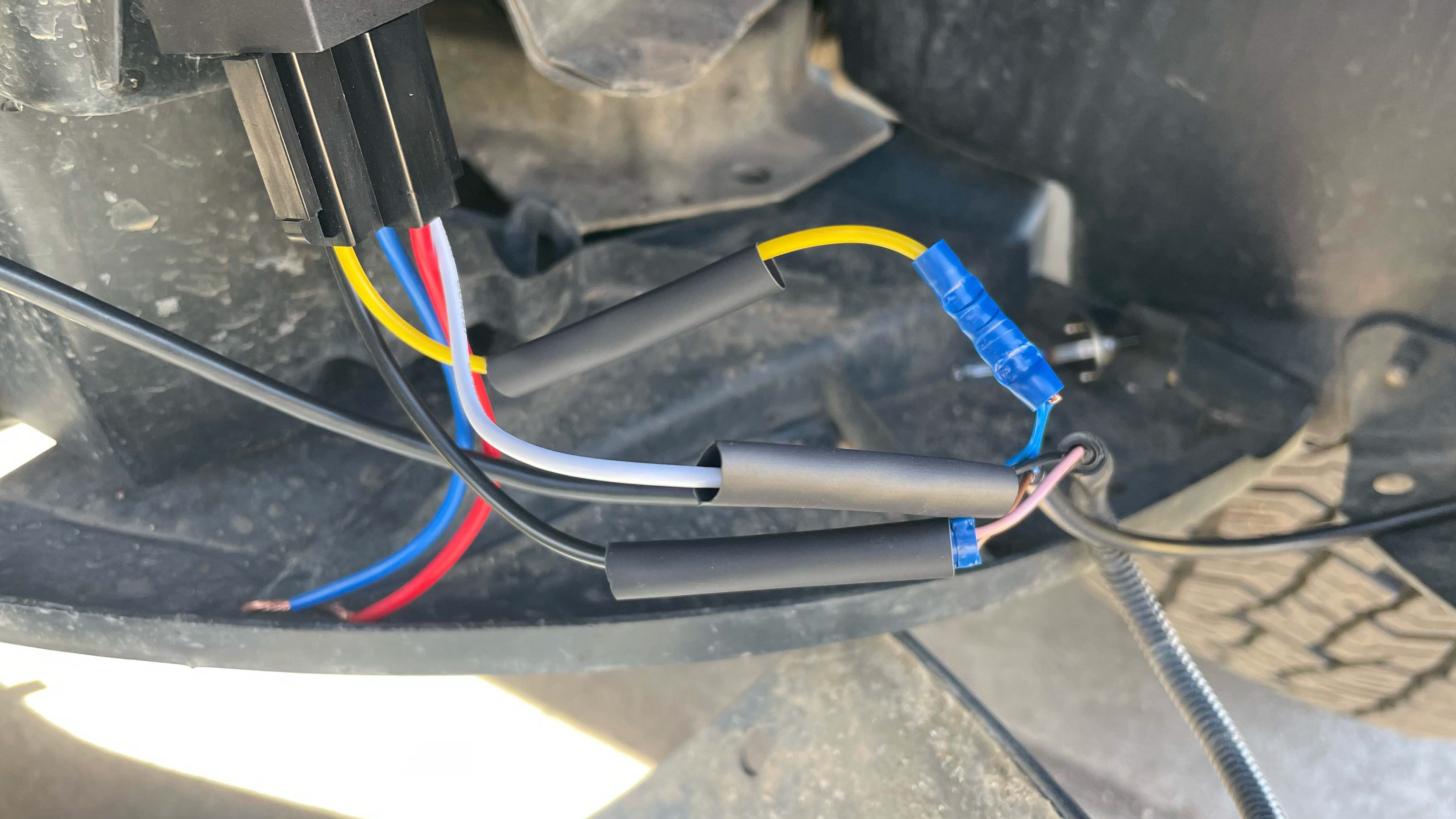
Crimping the wires together prior to heat shrink.

Right side wired and organized.
Left side wired and organized.
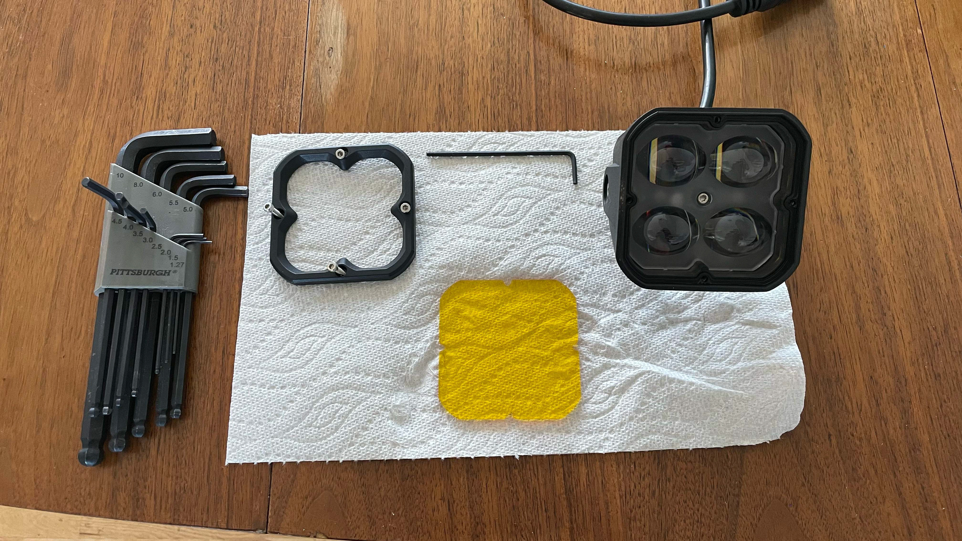
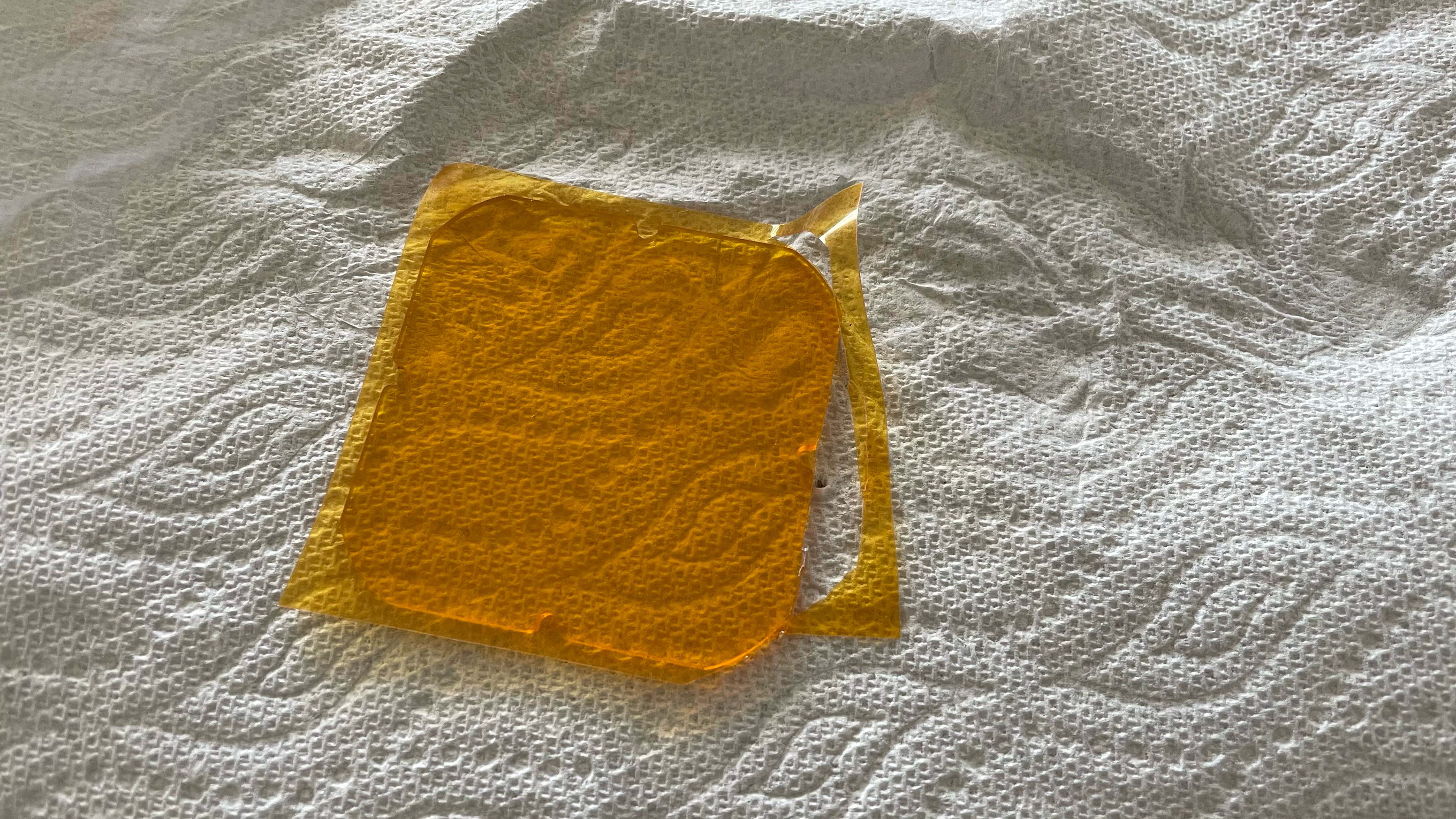
The final step before assembly was to add a film to the pod lights. This was done for two reasons: 1) to protect the lens from minor rock chips and 2) to tint the color to a slightly more amber tone. I disassembled the pod lights, removed the lenses, and cut out small squares of amber film to fit the shape. The film was applied from one end to the other to remove as many bubbles as possible before getting trimmed by a sharp knife and reassembled into the light. I applied a small amount of synthetic grease to the fasteners to make sure they are still easy to remove after operating in a highly corrosive environment.
With all of the prep work out of the way, the lights were assembled into the housings, into the bumper, and onto the car. The pigtails were plugged into the connectors which were previously wired, and the two-tone foglights worked just as designed.
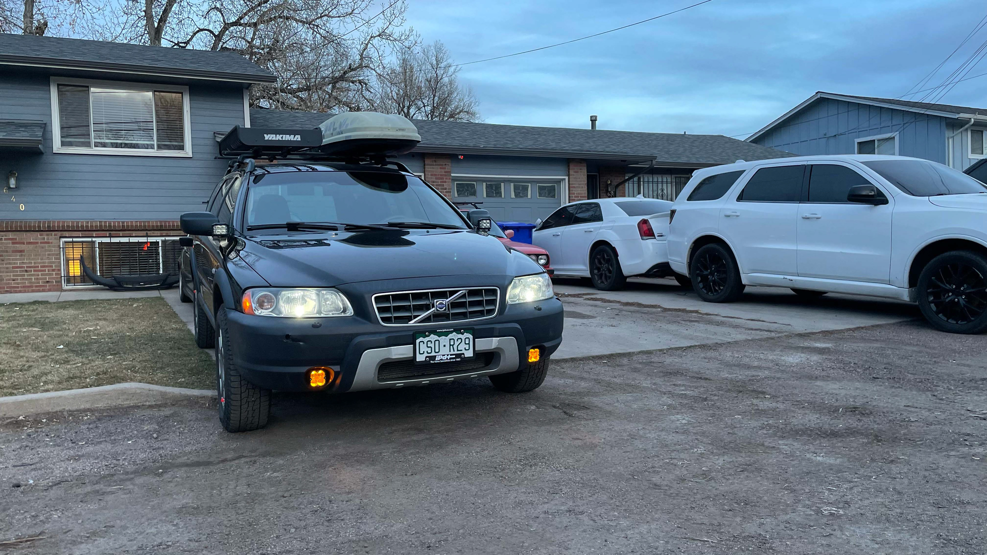
Final test of the fog light backlight feature.
Final test of the fog lamps.
SPOT LIGHTS
Determinations are still being made on the plan for the spot lights. This section will be updated after the build is complete.