About the Series
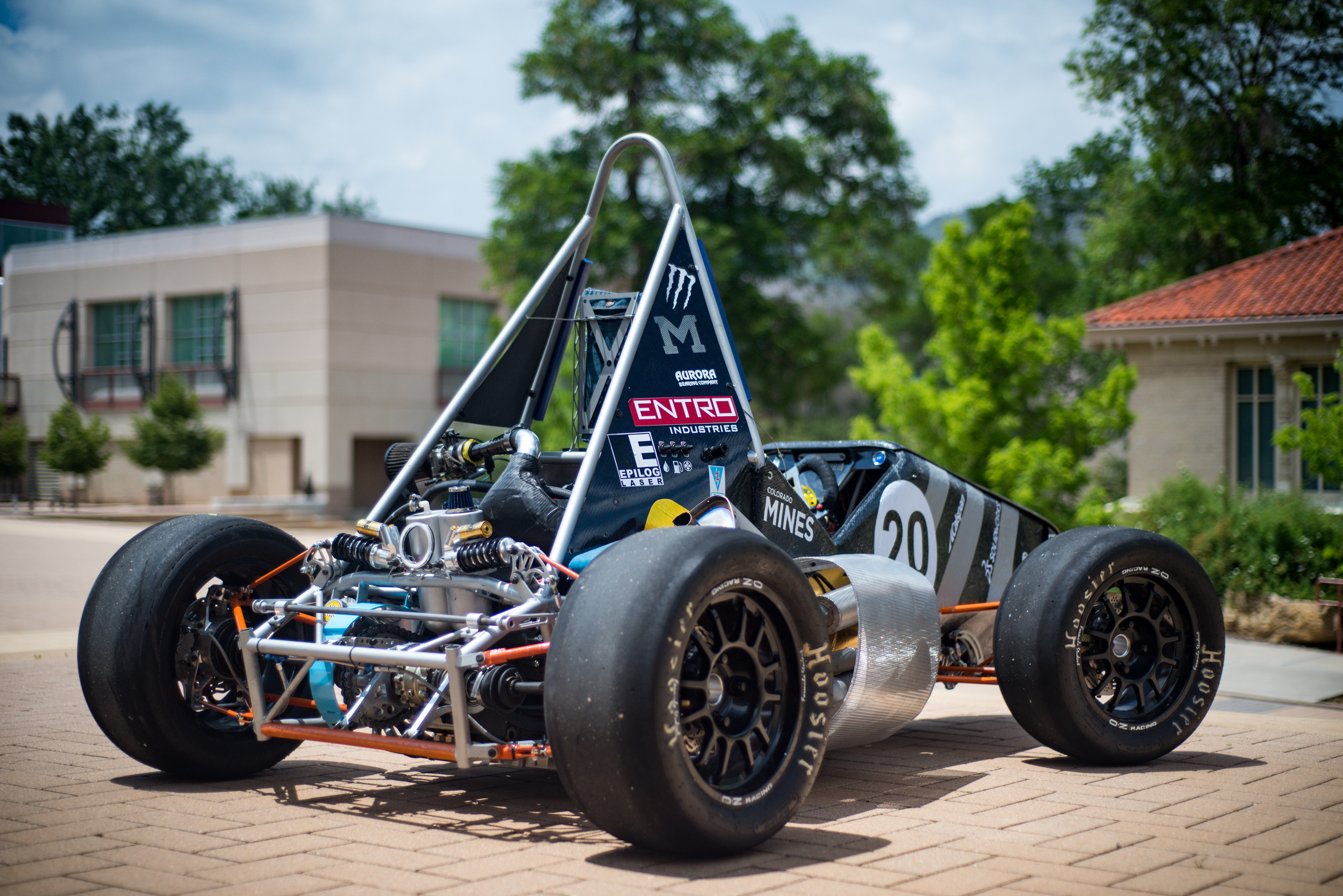
Formula SAE is a collegiate competition series hosted by SAE International. The purpose of the competition is to design and build a small, open-wheel racecar which is raced against other universities.
The competition puts a strong emphasis on engineering design and manufacturability. Every design is guided by a rational decision which can be traced back to the overall goals of the vehicle. Additionally, a cost report and business presentation ensure that the designs are practical for mass-production.
During my time on FSAE, I held several positions including designer, subsystem lead, and interim lead engineer. Several of the major projects I took on are discussed in the sections below.
Hub Design | 2018-2019
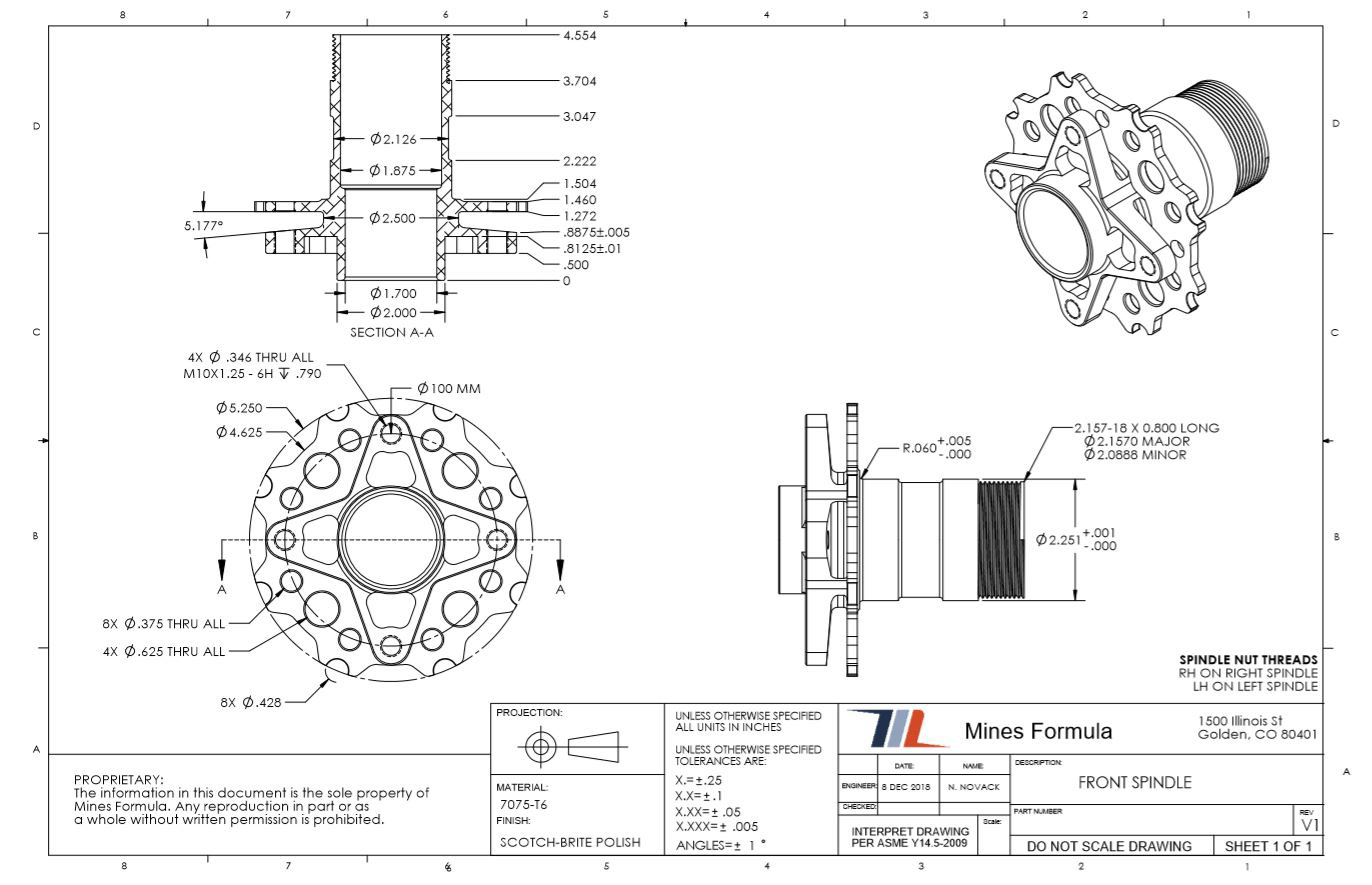
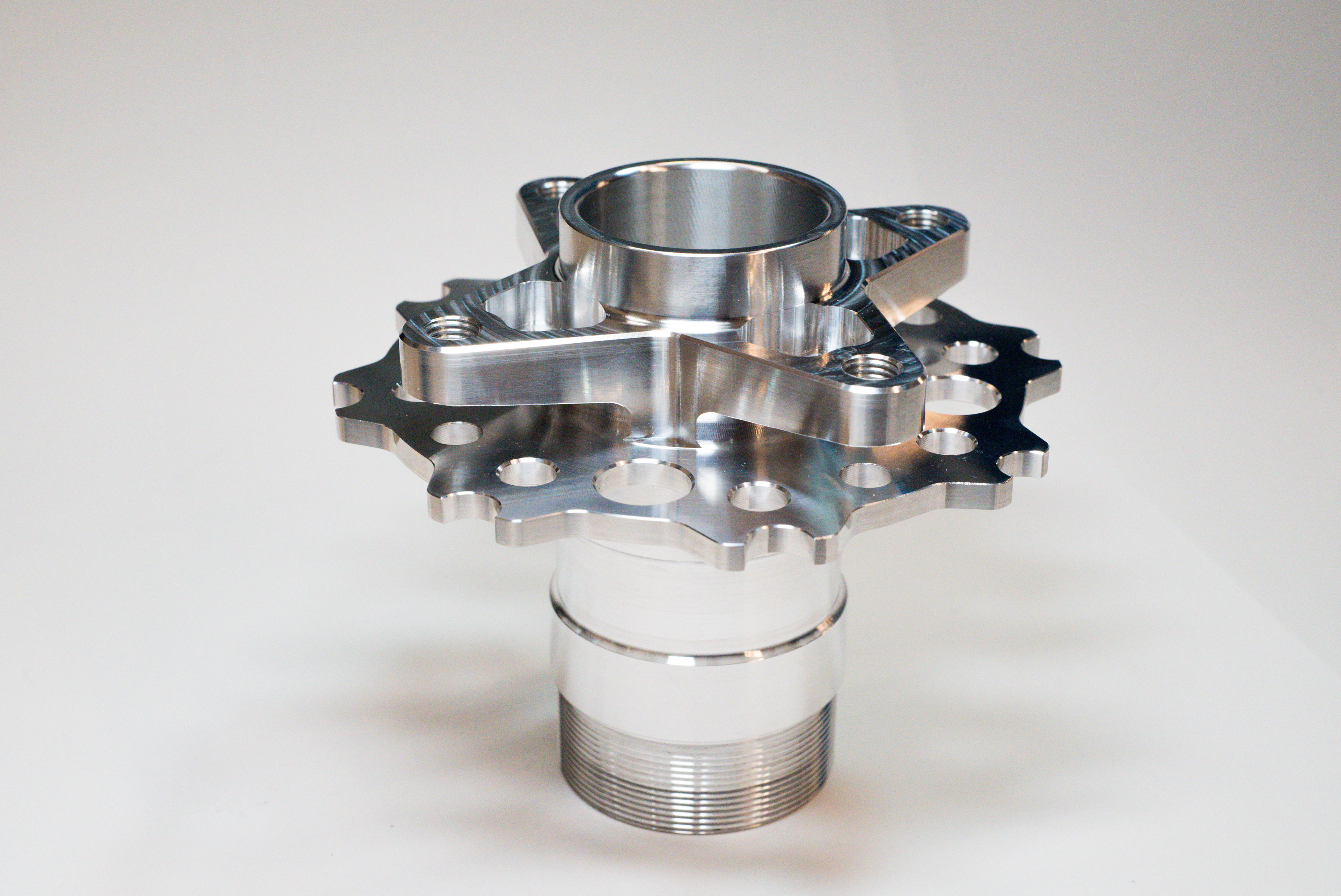
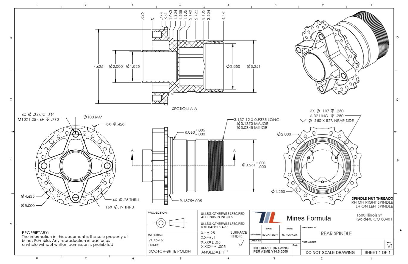
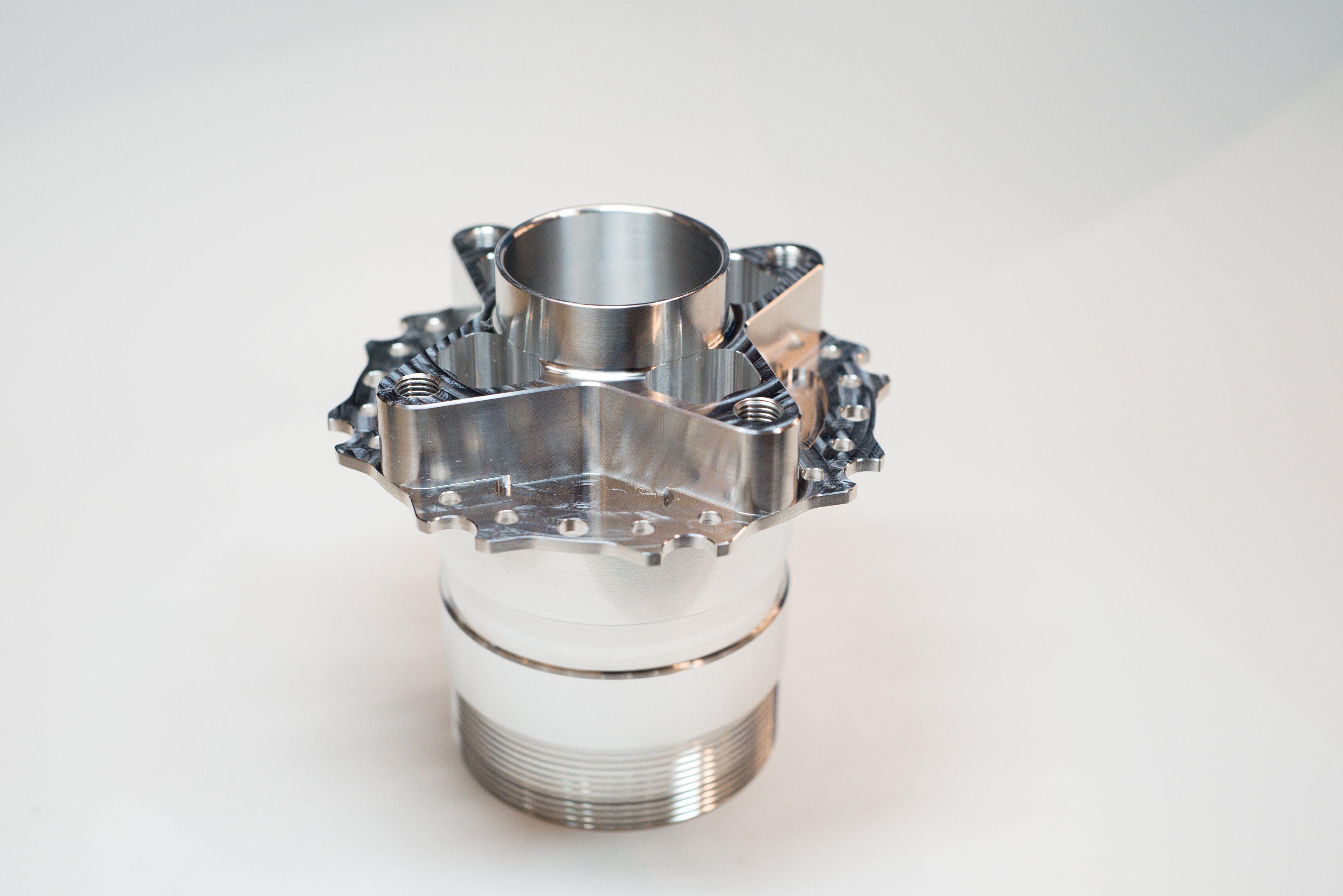
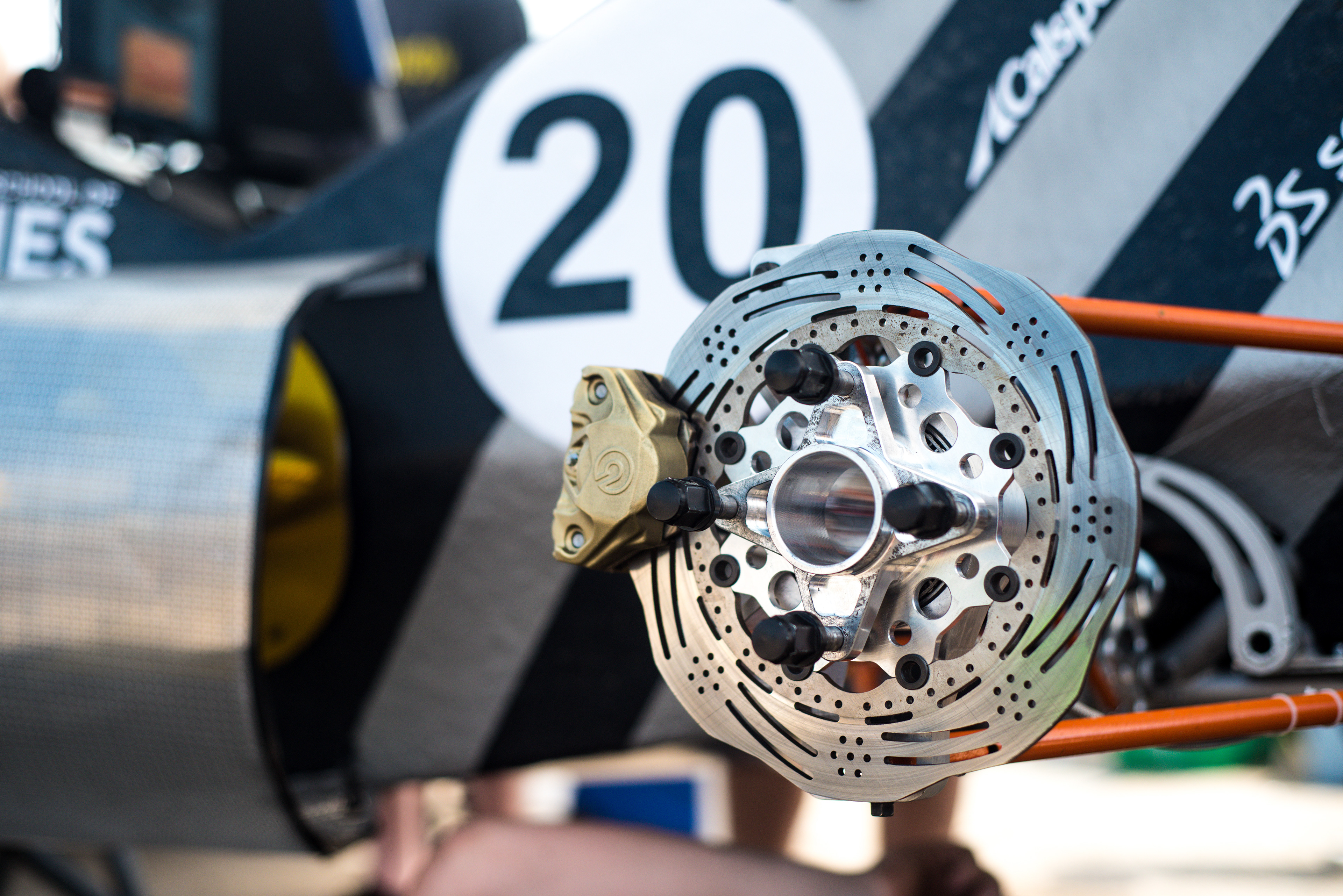
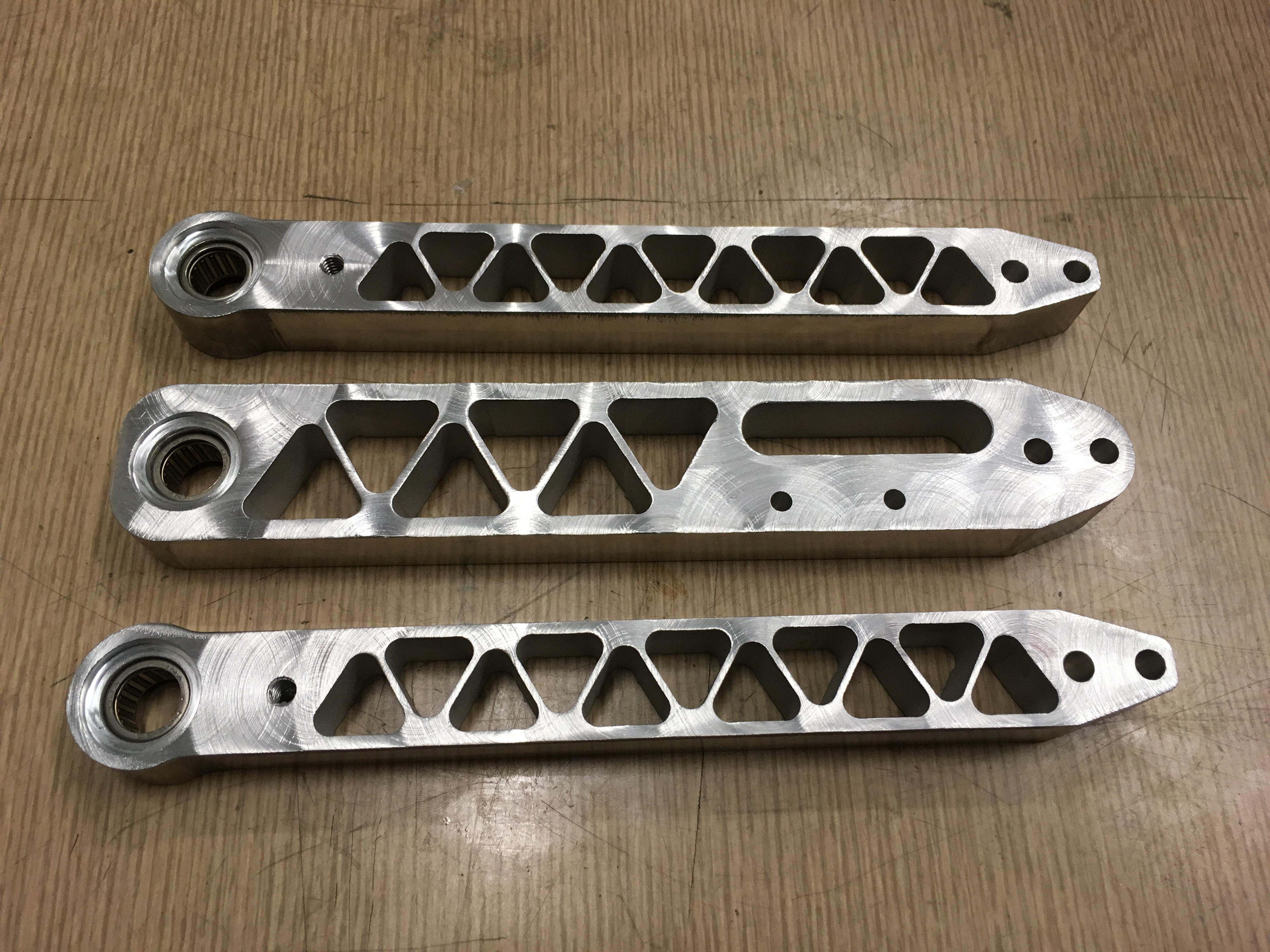
In the 2018-2019 season, my primary project was designing the wheel hubs. These components are responsible for allowing the wheel to rotate and transferring loads from the tire to the suspension. For years, the team opted to run off-the-shelf steel hubs. Although these were strong and durable, they were relatively heavy and limited the design of critical suspension parameters. For the 2018-2019 season, the decision was made to switch to in-house-designed aluminum hubs; the purpose for making this decision was to reduce unsprung rotating mass and to increase the bearing spacing for better wheel rigidity.
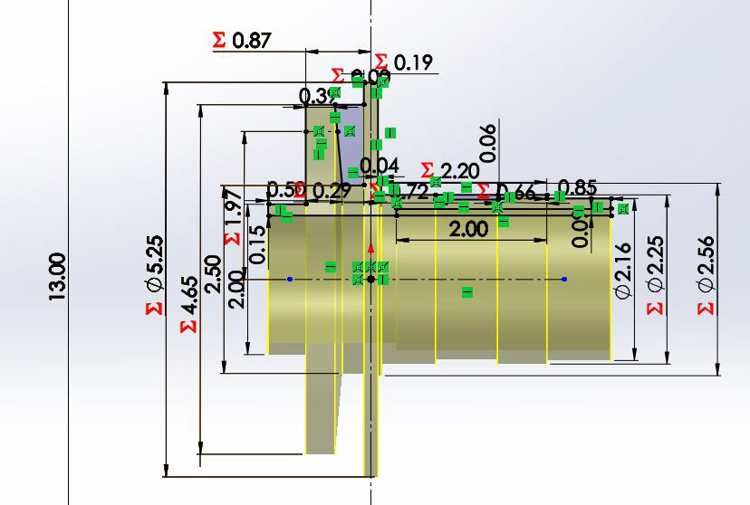
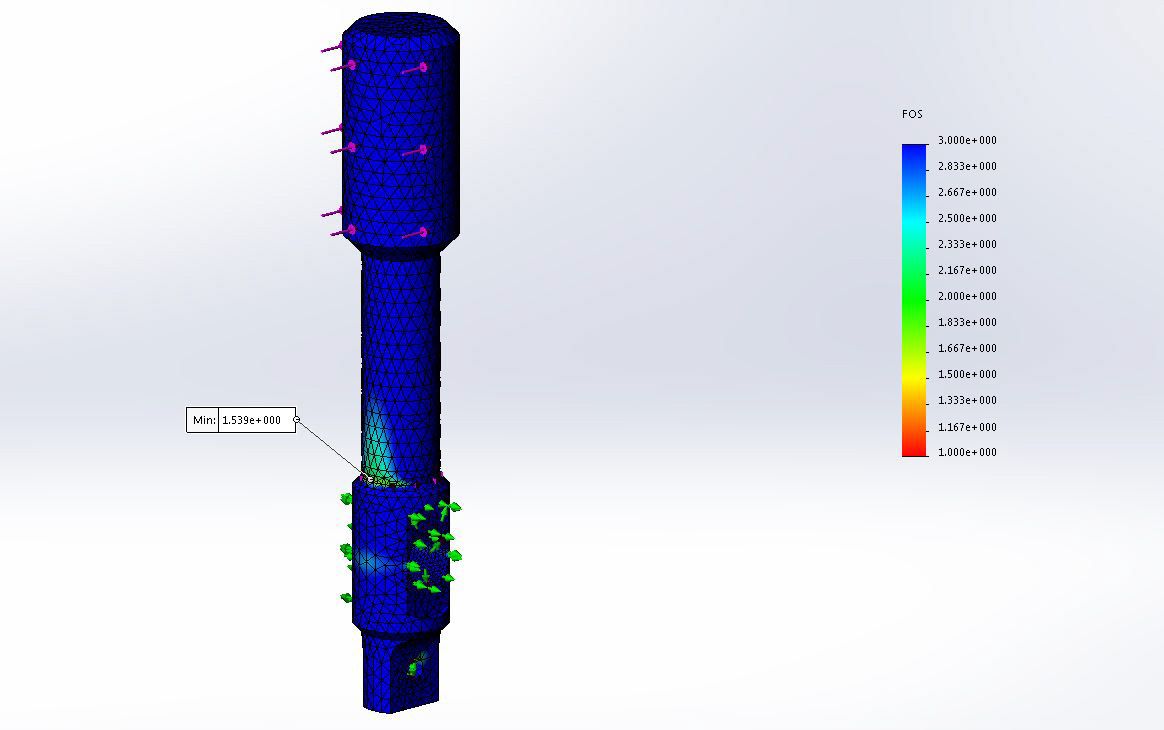
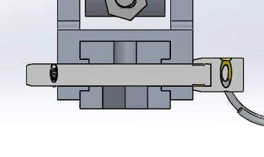
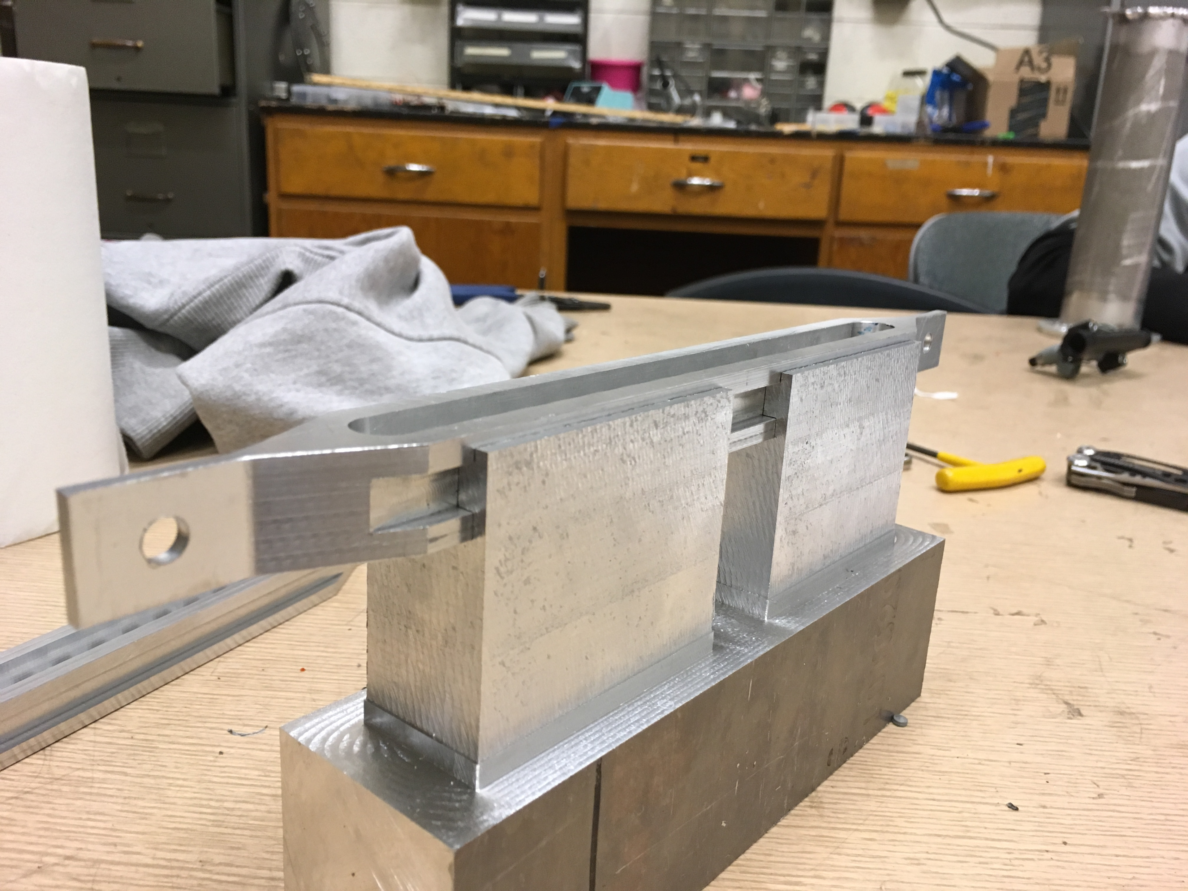
The first step in designing the spindles was creating a modular base sketch which allows the geometry to quickly adapt to changes made by interfacing components. Additionally, this sketch was set up with the manufacturing process in mind. It was decided early in the process that the hubs would first be machined on a CNC lathe to hold tight radial tolerances, then loaded into a CNC mill to complete the rest of the operations. The team has access to CNC mills, but not CNC lathes, so the first operation would need to be outsourced. To simplify the operations for the machine shop, the parts were modeled such that the features were grouped together into different machining operations: one for the as-turned part, a second for the first milling operation, and a third for the second milling operation. This allows the part to be rolled back and forward to view the sequential steps of its machining operations.
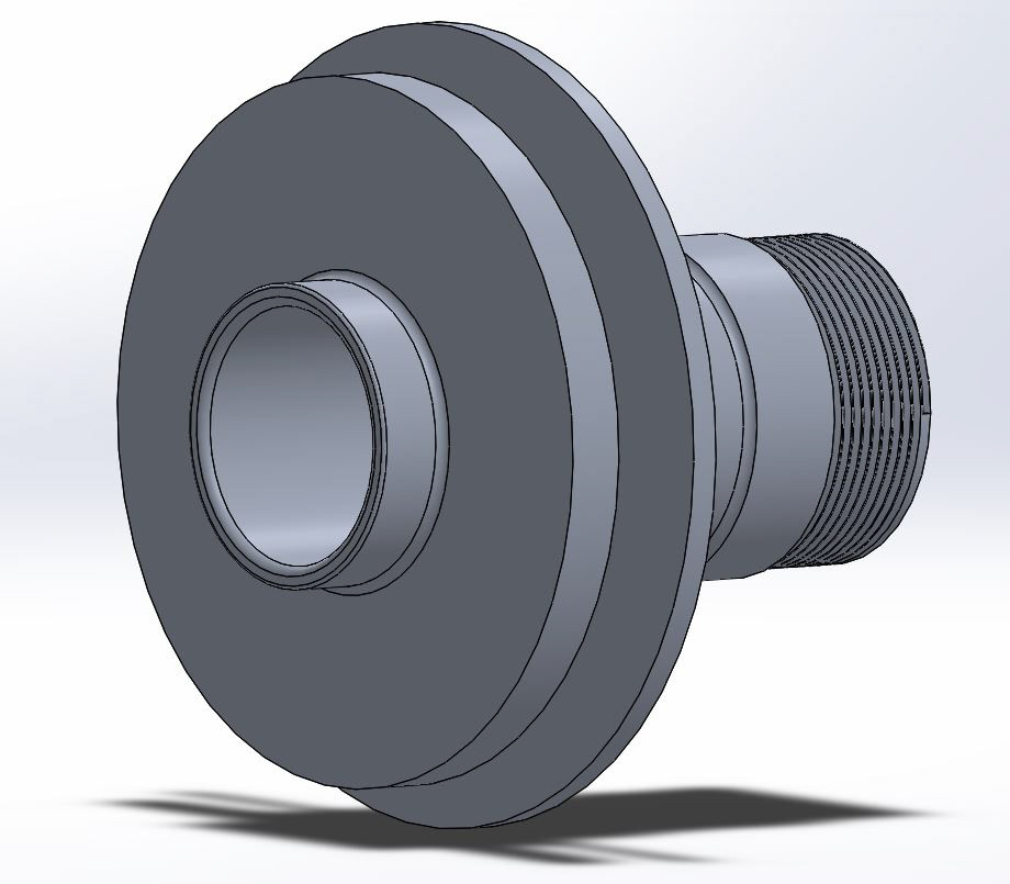
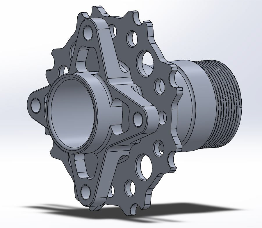
Once the part was modeled, it was checked for fitment against its interfacing components, and necessary adjustments were made. After running structural simulations and iterating several times, prints were finalized and sent to the machine shop along with the bar stock. Following delivery, the parts were inspected, installed on the vehicle, and tested. In accordance with the goals of the project, the mass was reduced by roughly 50 pct and the wheel compliance was eliminated.

Ergonomics Subsystem | 2016-2017
For the 2016-2017 season, a major emphasis was placed on designing with specific intent and building a vehicle which could complete the 20+ km endurance race. The prior vehicle was fast, but very flawed. A hose clamp failure led to the fuel pump disconnecting during the endurance race, starving the engine of fuel. Additionally, it was noted that the vehicle was well-built, but not well thought-out regarding overall system design and validation. With those shortcomings, the team decided to re-think all subsystems and put together extensive design documentation for future teams.
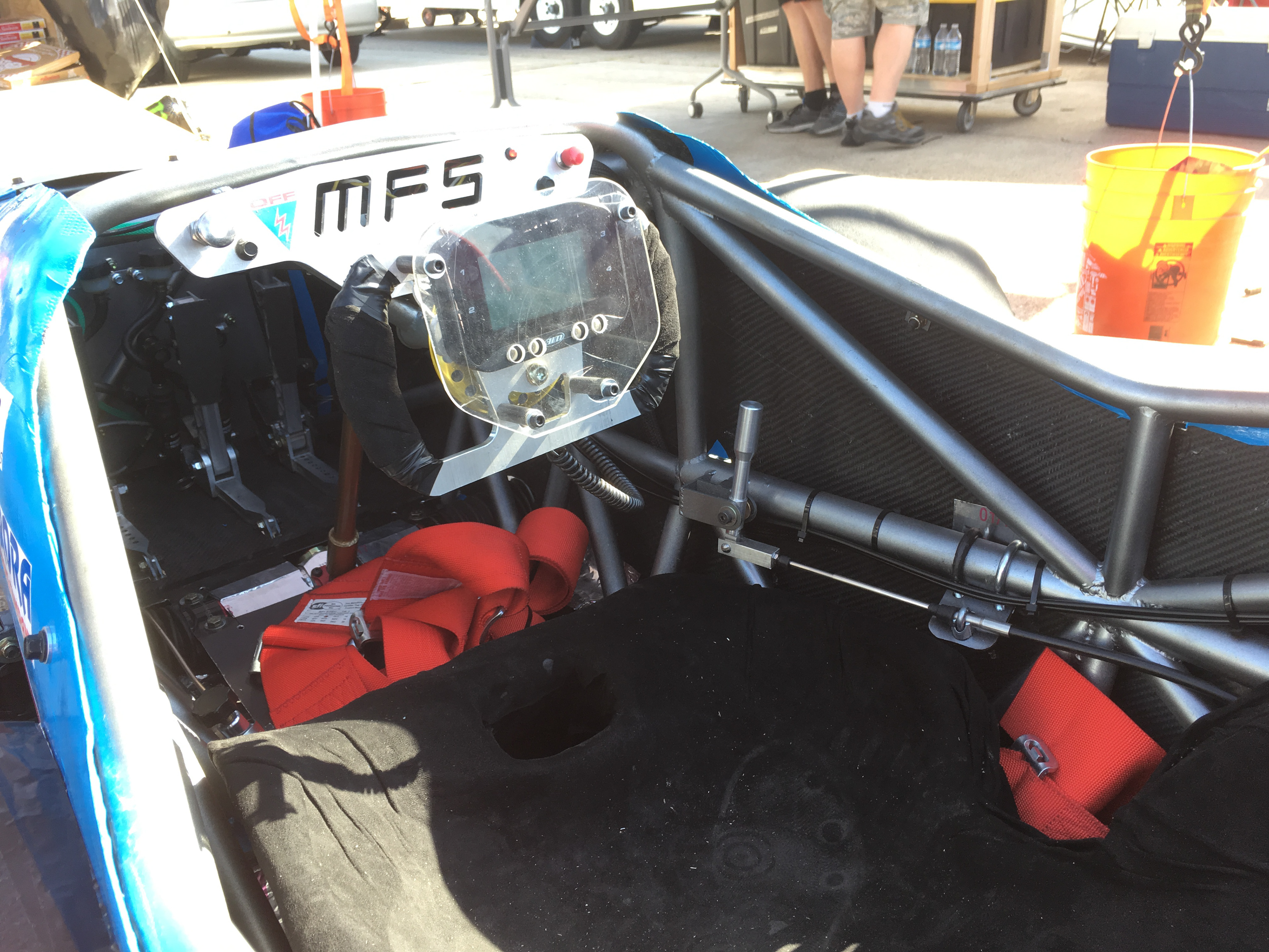
Following the 2016 competition, I was tasked with the responsibility of leading the ergonomics subsystem. This involves all components which the driver directly interacts with, most notably the steering wheel, the pedal box, and the shifting system. The goals for the vehicle were to increase reliability of components and to increase intuitiveness for the driver, demanding a major overhaul for the ergonomics subsystem.
Steering System
The steering system was not particularly flawed, but there was no documentation or reasoning behind most of the designs, particularly the steering column. The steering column is responsible for transferring the torsional input from the steering wheel to the steering rack. The steering rack was placed by the suspension subsystem, and the steering wheel was angled toward the driver's head for the most natural feeling. In order to accommodate the angular misalignment, a double-sided U-joint was selected. U-joints are excellent for solving angular misalignment, but must be used in pairs and properly phased in order to cancel out the sinusoidal relationship between the input and output. The double-sided U-joint includes both joints in one unit to decrease cost, eliminates manufacturing error by pre-phasing the pair, and minimizes operating angles to increase service life and decrease the sinusoidal effects of any error present. Because the U-joints are machinable, various tube sizes and materials were considered by writing a code in MATLAB which directly compares commercially-available tubes. This code has been continuously modified and is still being used by the 2019-2020 team.
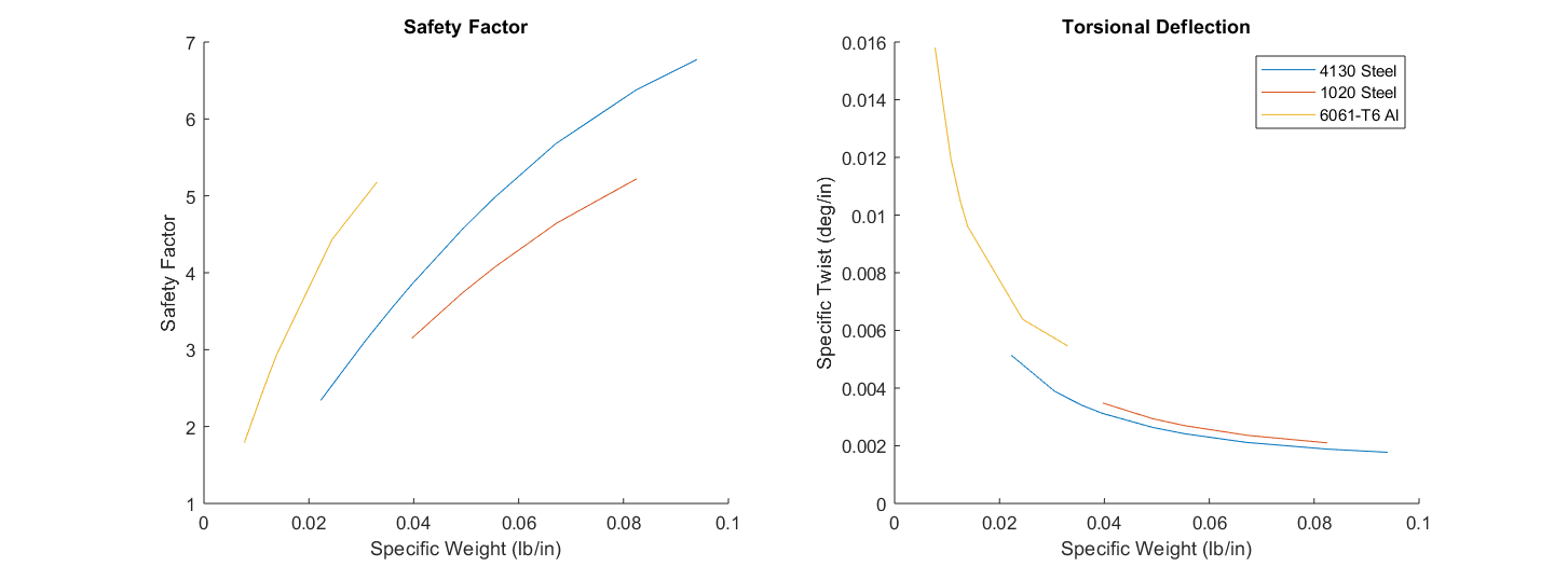
Plots used to help determine tube size and material for the steering column.
Shifting System
The shifting system was a major point of focus for the 2017 vehicle. The 2015 vehicle used a lever shifter with an integrated hand clutch, which worked, but was not intuitive for the driver to use. The 2016 vehicle implemented paddle-operated cables, which were very intuitive to use, but were very prone to fraying and too heavy for the driver to operate. In line with the goals of the overall vehicle, the team decided to use a foot clutch and a hand lever. This design is similar to a standard road car, so there is a relatively small learning curve. Additionally, the hand lever operates a push-pull cable, which simplifies the system and eliminates the cable-fraying concerns.
The design began by using a fish scale to measure both the torque required to shift the engine as well as the desired driver shifting force. These were input into a MathCAD document which calculated the proper lever ratio for the hand lever. From there, appropriate travel lengths were determined to lock in the final geometry, and a CAD model was developed by a member of the subsystem. The part was analyzed using finite element analysis and iterated to the final design, which was manually machined on a lathe and a Bridgeport mill.

The shifter operated properly at competition, making the 2017 car the university's first to shift gears in the autocross and endurance races. The one design issue was a bending fatigue failure on the push-pull cable, which was temporarily fixed by re-tapping the threads. Later designs focused more on cable mounting positions to reduce the bending load and prolong the time to cause a fatigue failure.
Pedal Box
The pedal box in the 2016 competition vehicle was a major upgrade from previous years, switching to a lightweight two-pedal design with each pedal on its own individual rail. This concept allowed better control over pedal position and significantly reduced weight over previous designs by eliminating the large carrier platform. However, the pedals were fairly bulky and adjustment times were lengthy due to the use of a bolt which connected the pedals to the rails. For the 2017 vehicle, several goals were set for the new pedal box: quicker adjustment times, lighter weight, and the addition of a clutch pedal for the new shifting system.
The design began by measuring the leg lengths of the tallest and shortest drivers to determine the maximum amount of adjustability required. This determined the length of the rails as well as the distance between consecutive pedal positions. The second step was brainstorming and deciding on a new system of adjustment. After several concepts, the team decided to switch to a pinned-slotted design: rather than bolting the pedal carrier onto the rail, the pedal carrier rides along the rail using horizontal slots and pins into discrete locations.
Once these parameters were st, the detailed design was tasked to a small group of newer members. The designs were realized in CAD and analyzed using finite element analysis. Once the regions of higher stress were identified, the designs were modified accordingly; this cycle continued until the assembly was brought down to the target weight.

The manufacturing process was more intensive than in previous years, but well within our means. Blanks for the pedals were cut on a waterjet and post-machined to hit the tight tolerances around the bearing pockets. The pedal carriers were CNC-machined to create the plan-view profile, then sent to the Bridgeport to machine the slots. The pedal carriers were fully CNC-machined in several operations. The slots on the carriers were machined using a key-slot cutter, and the pedal rails were checked for fitment in the machine to ensure assembly of all the components was possible.
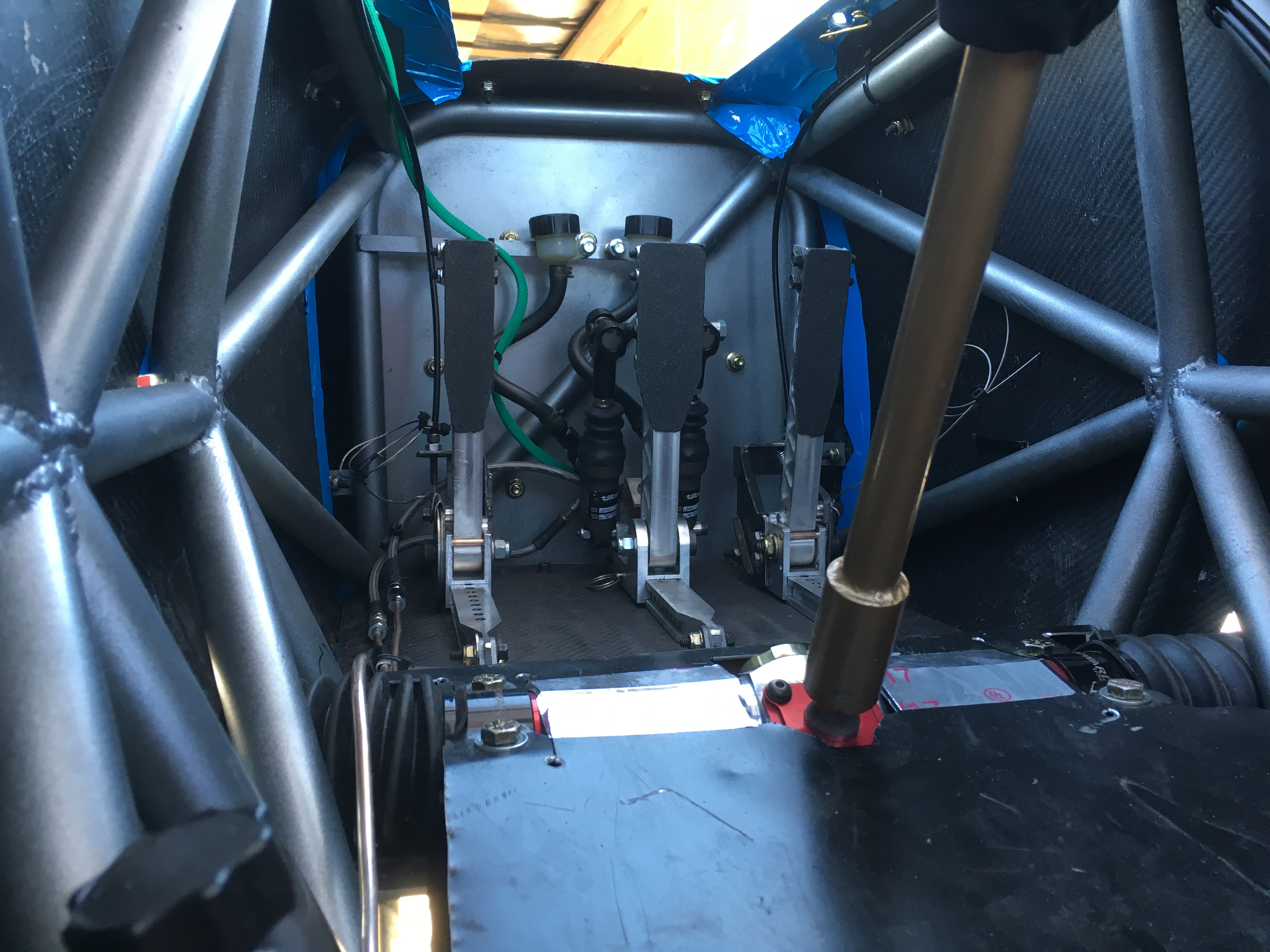
Altogether, the system worked well. Drivers were satisfied with the pedal positions and adjustability, and the system came in with a lighter weight than the previous design, despite adding another pedal. However, several flaws were noted. Although the slots worked well initially, galling occurred over time and made pedal adjustments more difficult. Additionally, the cam design used to actuate the cables for the clutch and throttle were fairly heavy, prone to deflection, and difficult to manufacture. All of these flaws have been documented, and the design has been modified on following vehicles to address these issues.